Integrated cantilever rotor structure

A cantilever rotor and one-piece technology, applied in the direction of blade support components, jet propulsion devices, engine components, etc., can solve the problems of complex mechanical structure, low reliability, power consumption and other problems of the unit, and achieve shortened cantilever length, reliable use, Effect of reducing vibration amplitude

Inactive Publication Date: 2012-05-02
HARBIN DONGAN ENGINE GRP
View PDF10 Cites 10 Cited by
  • Summary
  • Abstract
  • Description
  • Claims
  • Application Information

AI Technical Summary

Problems solved by technology

Although there is no need for a deceleration device, the use of conventional connection structures, such as couplings, will result in complex

Method used


Image

  • Integrated cantilever rotor structure
  • Integrated cantilever rotor structure

Examples


Embodiment Construction

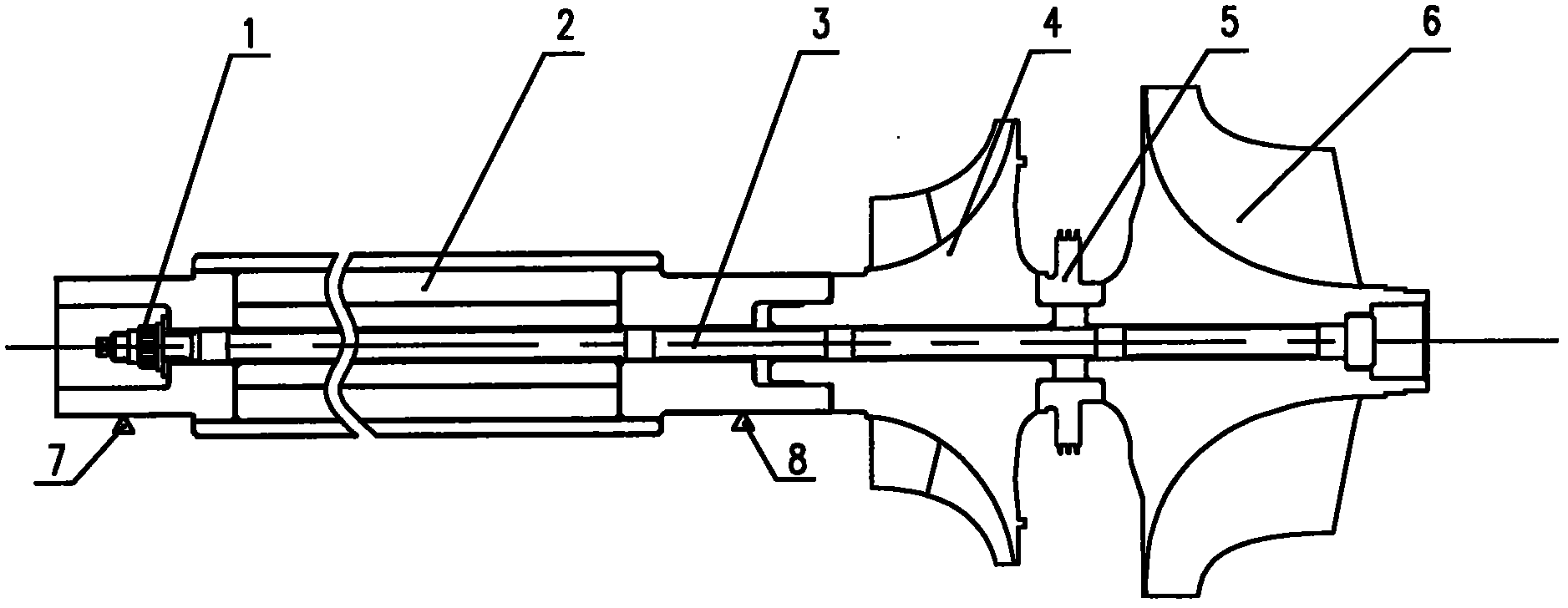
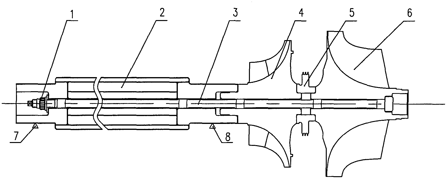
[0008] As shown in the figure, the integrated cantilever rotor structure includes generator rotor 2, centrifugal compressor impeller 4, sealing grate teeth 5, and radial turbine impeller 6 arranged in sequence on the center tie rod 3. The centrifugal compressor impeller 4 One side of the centrifugal compressor impeller 4 and the radial turbine impeller 6 are connected back to back through the sealed grate teeth 5 and the radial turbine impeller 6 in the manner of end face matching, and the other end of the centrifugal compressor impeller 4 is connected to the power generation The central tie rod 3 runs through the generator rotor 2, the centrifugal compressor impeller 4, the sealing grate 5 and the radial turbine impeller 6, and one end is provided with a boss and connected to the inner hole of the radial turbine impeller 6. Step fit, the other end is provided with threads and fixed by the lock nut 1, and the two sides of the generator rotor are respectively provided with suppo...


PUM


Abstract

The invention relates to an integrated cantilever rotor structure, which comprises a generator rotor, a centrifugal compressor impeller, sealed grate teeth and a radial turbine impeller which are arranged on a central pull rod in sequence. One side of the centrifugal compressor impeller is connected with the radial turbine impeller through the sealed grate teeth in end face matching mode, the centrifugal compressor impeller and the radial turbine impeller are arranged in back-to-back mode, and the other end of the centrifugal compressor impeller is connected with the generator rotor. The integrated cantilever rotor structure has the advantages of being simple in structure, small in volume and capable of enabling a unit structure to be simple, usage to be reliable, failure rate to be low and both manufacture cost and maintenance cost to be reduced.

Description

technical field [0001] The invention relates to an integrated cantilever rotor structure. Background technique [0002] The generator and the gas generator of the gas turbine generator set are usually connected by a reducer or a coupling. Micro gas turbine generator set is a new technology developed rapidly in recent years, characterized by small size and high speed of the unit. At present, a high-speed permanent magnet motor (patent application number: 201020502094.X) has been successfully developed. Its working speed can reach 60000r / min. It can be directly connected with the gas generator and can generate electricity normally without deceleration. Although there is no need for a deceleration device, the use of conventional coupling structures, such as couplings, will result in a complex mechanical structure, large volume, and low reliability during work, and a large amount of power will be consumed in mechanical transmission. Contents of the invention [0003] The pur...

Claims


Application Information

Patent Timeline
IPC IPC(8): F01D5/02F02C7/36F02C3/04
Inventor 何民刘丛红黄国权时晓军冯占祥孙海龙脱烨刘莉娜
Owner HARBIN DONGAN ENGINE GRP
Why Eureka
Try Eureka