Bone fusion device

a bone fusion and bone technology, applied in the field of bone fusion devices, can solve the problems of degenerative disc disease, pain that radiates into other parts of the body, and may cause instability of the vertebrae, and achieve the effect of increasing the surface area

Active Publication Date: 2013-10-17
NEUROPRO TECH
View PDF65 Cites 160 Cited by
  • Summary
  • Abstract
  • Description
  • Claims
  • Application Information

AI Technical Summary

Benefits of technology

[0013]The present invention is directed to a bone fusion device for insertion between bones that are to be fused together, such as, for example, the vertebrae of a spinal column. The bone fusion device comprises at least one extendable tab and one or more tab extension assemblies. Each tab extension assembly is able to be adjusted in order to individually control the extension or contraction of a side of the tab thereby enabling adjustment of the height and / or angle of the tab with respect to the body of the bone fusion device. The bone fusion device is in its most compact state when the tab is aligned with the body of the device such that the tab lies within the exterior of the body of the device. In this compact form, the bone fusion device is preferably inserted between the vertebrae by using an arthroscopic procedure. After the device has been positioned between the vertebrae, the tab is extended using the extension assemblies such that the tab abuts the bottom surface of the upper vertebrae. The angle of the tab with respect to the body of the device is able to be adjusted such that it corresponds to the vertebrae. Specifically, each extension assembly is able to be individually adjusted such that the side controlled by each assembly is raised or lowered until the desired tab angle is achieved. In this way, the tab is advantageously positioned and angled to correspond to the vertebrae to help brace the device until the bone has fused and to provide a larger surface area to which the bones attach and fuse during a healing period.

Problems solved by technology

Injury, disease, or excessive pressure on the discs can cause degenerative disc disease or other disorders where the disc becomes thinner and allows the vertebrae to move closer together or become misaligned.
As a result, nerves may become pinched, causing pain that radiates into other parts of the body, or instability of the vertebrae may ensue.
Such an invasive surgical procedure requires a long recovery period.

Method used


Image

  • Bone fusion device
  • Bone fusion device
  • Bone fusion device

Examples


Embodiment Construction

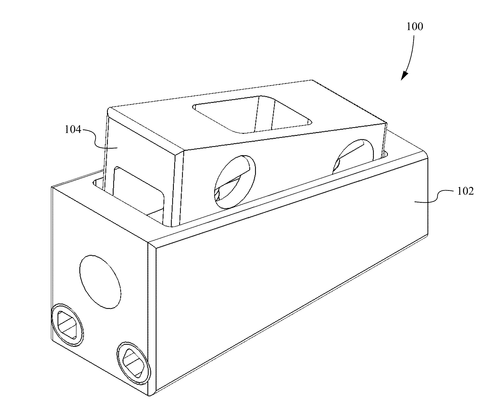
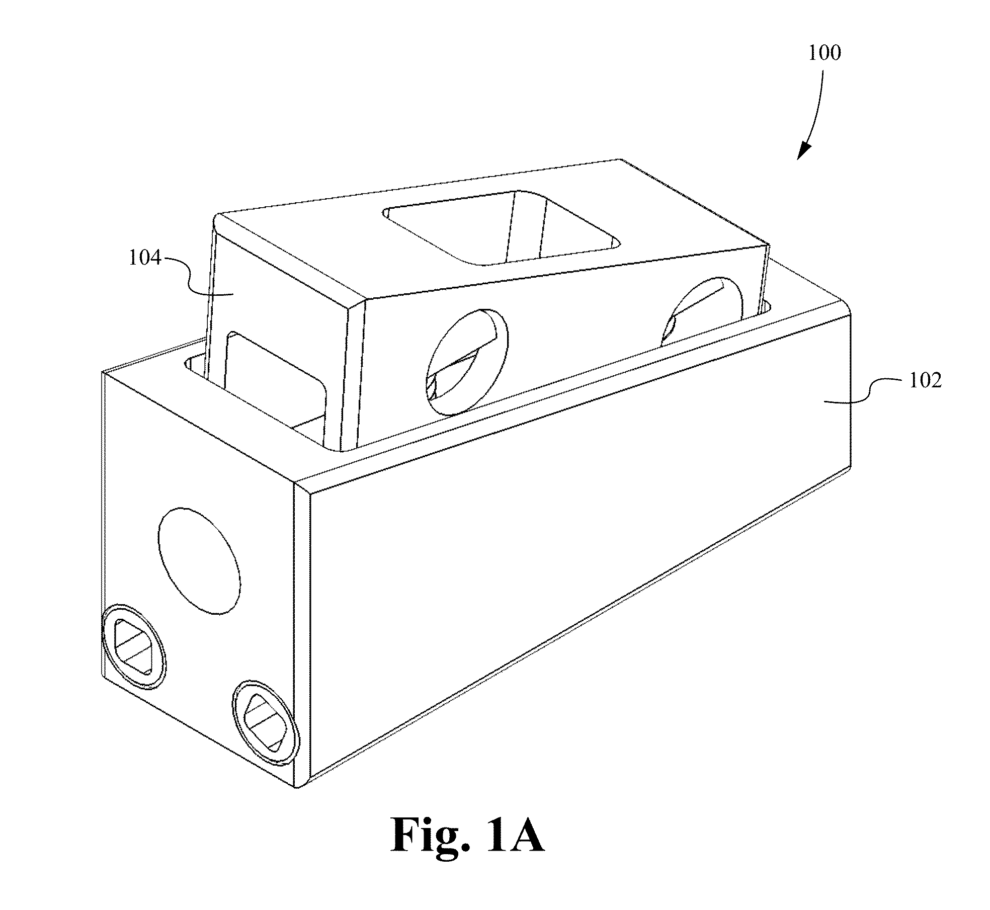
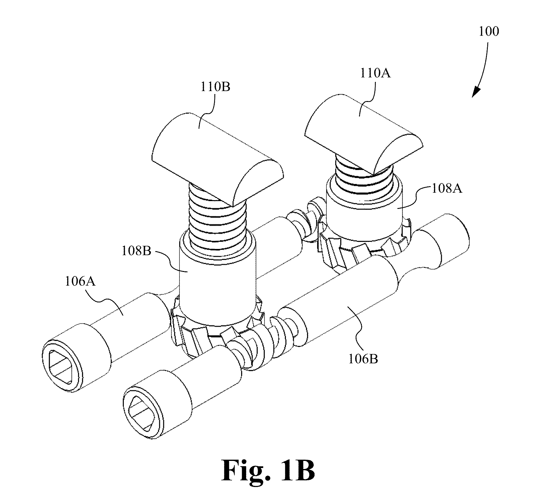
[0059]In the following description, numerous details and alternatives are set forth for purpose of explanation. However, one of ordinary skill in the art will realize that the invention can be practiced without the use of these specific details. For instance, the figures and description below often refer to the vertebral bones of a spinal column. However, one of ordinary skill in the art will recognize that some embodiments of the invention are practiced for the fusion of other bones, including broken bones and / or joints. In other instances, well-known structures and devices are shown in block diagram form in order not to obscure the description of the invention with unnecessary detail. Further, although the figures and description below refer to a bone fusion device having a single tab and a pair of tab extension assemblies, it is understood that the bone fusion device is able to comprise multiple tabs each having any number of tab extension assemblies.

[0060]FIGS. 1A and 1B illustr...


PUM

PropertyMeasurementUnit
distanceaaaaaaaaaa
angleaaaaaaaaaa
rotationaaaaaaaaaa

Abstract

A bone fusion device for insertion between bones that are to be fused together, such as, for example, the vertebrae of a spinal column. The bone fusion device comprises at least one extendable tab and one or more tab extension assemblies. Each tab extension assembly is able to be adjusted in order to individually control the extension or contraction of a side of the tab thereby enabling adjustment of the height and / or angle of the tab with respect to the body of the bone fusion device. Each tab extension assembly is able to be individually adjusted such that the side controlled by each assembly is raised or lowered until the desired tab angle is achieved. The tab is advantageously positioned and angled to correspond to the vertebrae to help brace the device until the bone has fused.

Description

RELATED APPLICATIONS[0001]This application claims priority under 35 U.S.C. §119(e) of U.S. Provisional Patent Application Ser. No. 61 / 624,155, filed Apr. 13, 2012, and entitled “BONE FUSION DEVICE,” which is hereby incorporated by reference.FIELD OF THE INVENTION[0002]This invention relates generally to bone fusion devices. More specifically, the present invention relates to devices for fusing vertebrae of the spine that can be inserted arthroscopically.BACKGROUND OF THE INVENTION[0003]The spinal column is made up of vertebrae stacked on top of one another. Between the vertebrae are discs which are gel-like cushions that act as shock-absorbers and keep the spine flexible. Injury, disease, or excessive pressure on the discs can cause degenerative disc disease or other disorders where the disc becomes thinner and allows the vertebrae to move closer together or become misaligned. As a result, nerves may become pinched, causing pain that radiates into other parts of the body, or instabi...

Claims


Application Information

Patent Timeline
Patent Type & Authority Applications(United States)
IPC IPC(8): A61F2/44
CPCA61F2/447A61F2/4657A61F2/441A61F2/4465A61F2/4601A61F2002/2839A61F2002/30522A61F2002/30525A61F2002/30538A61F2002/30556A61F2002/30579A61F2002/30581A61F2002/30601A61F2002/30617A61F2002/448A61F2002/4661A61F2002/4666A61B2017/00398A61B2017/0256A61B2090/032A61B90/03A61B2090/061A61B2090/065A61B2090/0807A61F2/28
Inventor MCLUEN, GARY R.BAKER, DANIEL R.REMINGTON, BENJAMIN J.
Owner NEUROPRO TECH
Why Eureka
Try Eureka