Data transfer method and storage system adopting data transfer method
a data transfer and storage system technology, applied in the field of data transfer methods, can solve the problems of increasing costs and difficult to correspond to market trends, and achieve the effects of improving access performance and processing performance, reducing costs, and improving utilization ratio
- Summary
- Abstract
- Description
- Claims
- Application Information
AI Technical Summary
Benefits of technology
Problems solved by technology
Method used
Image
Examples
embodiment 1
[0051]The present embodiment (embodiment 1) is a preferred embodiment of a method for improving the performance of a computer system 100 by enhancing the efficiency of memory access. Now, the details of the present embodiment will be described with reference to the drawings.
[0052]
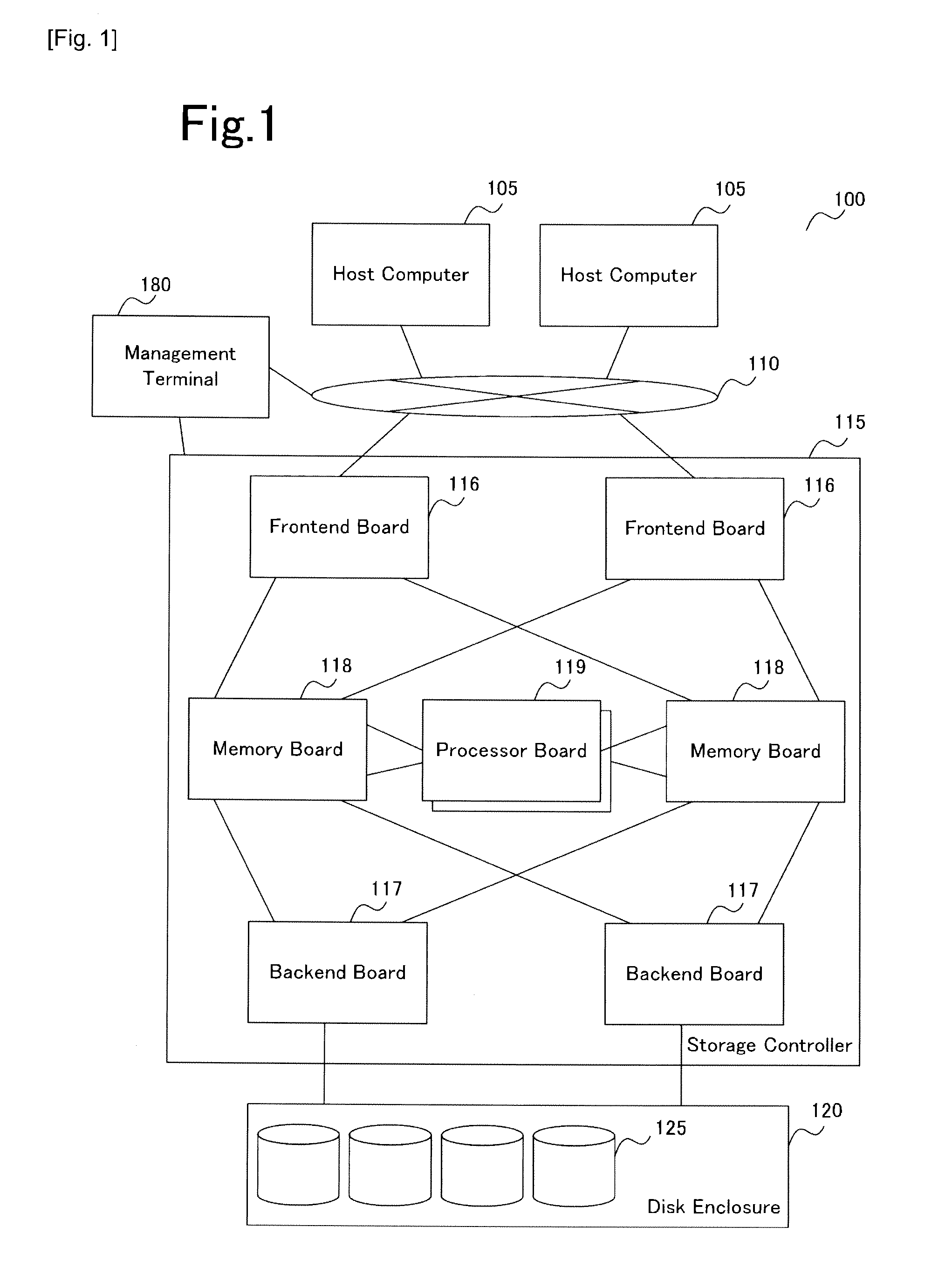
[0053]FIG. 1 is an example of a storage controller 115 to which the present invention is applied, and a computer system 100 including the storage controller 115. The computer system 100 includes a host computer 105 for performing data processing and computation, a storage controller 115, and a storage device 120 storing disks 125. There can be multiple host computers 105 and storage devices 120. The storage controller 115 and the storage device 120 as a set is called a storage system.
[0054]Generally, in a SAN (Storage Area Network), the host computer 105 and the storage controller 115 are coupled by a fiber channel or an Ethernet (Registered Trademark) and the like via a network 110 composed of a switch or ...
embodiment 2
[0267]FIG. 32 is a view showing the configuration of a storage system according to a second embodiment. In the configuration of a storage system 3200 according to embodiment 2, the configuration of a storage controller 3215 differs from the storage controller 115 of FIG. 1 according to the first embodiment, but the other arrangements are the same as the storage system according to embodiment 1. The configuration and processing of the second embodiment equivalent to the first embodiment are provided with the same reference numbers and the detailed descriptions thereof are omitted.
[0268]The configuration of the storage system according to the second embodiment will be described with reference to FIG. 32. Similar to the first embodiment, the storage system 3200 comprises a host computer 105, a storage controller 3215 and a storage device 120.
[0269]The storage controller 115 according to the first embodiment has the frontend board 116, the backend board 117 and the processor board 119 d...
embodiment 3
[0275]FIG. 34 is a view showing the configuration of a storage system according to the third embodiment. The configuration of the storage system 3400 according to the third embodiment is similar to the storage system of the first embodiment, except that the configuration of the storage controller 3405 differs from that of the storage controller 115 of FIG. 1 according to the first embodiment. The configurations and processes according to embodiment 3 equivalent to those of embodiment 1 are provided with the same reference numbers, and detailed descriptions thereof are omitted.
[0276]The configuration of the storage controller 3405 according to the third embodiment will be described with reference to FIG. 34. The storage system 3400 includes a host computer 105, a storage controller 3405 and a storage device 120 similar to the first embodiment.
[0277]According to the storage controller 115 of the first embodiment, the frontend board 116, the backend board 117 and the processor board 11...
PUM
 Abstract
Description
Claims
Application Information
 - R&D
- Intellectual Property
- Life Sciences
- Materials
- Tech Scout
- Unparalleled Data Quality
- Higher Quality Content
- 60% Fewer Hallucinations
Browse by: Latest US Patents, China's latest patents, Technical Efficacy Thesaurus, Application Domain, Technology Topic, Popular Technical Reports.
© 2025 PatSnap. All rights reserved.Legal|Privacy policy|Modern Slavery Act Transparency Statement|Sitemap|About US| Contact US: help@patsnap.com


