
Pipe inspection system

Active Publication Date: 2013-10-24
LOFSTROM DANIEL
View PDF3 Cites 6 Cited by
  • Summary
  • Abstract
  • Description
  • Claims
  • Application Information

AI Technical Summary

Benefits of technology

The present invention provides a tool and method for inspecting a pipe with a feeder tube extending from a header pipe. The tool includes a head piece with a camera or sensing device mounted inside, which can provide a field of view through the distal opening. The head piece can also have one or more jacks to sealably couple with the peeper tube. The tool can also include a tube coupler oriented at an angle with respect to the head piece, which can be pressed against an interior surface of the pipe to sealably couple with the peeper tube. The technical effect of this invention is to provide a more efficient and effective way to inspect pipes with feeder tubes extending from them.

Problems solved by technology

Some of this piping is located in environments that are difficult to access for inspection or repair.
The pipe geometry itself, however, can make inspection difficult even for a sophisticated PIG.
Also, PIGs are not capable of navigating pipe sections of significantly differing diameters.
This practice, however, is expensive to perform, takes a facility offline for a relatively long time, and poses the risk that the patch will fail.

Method used


Image

  • Pipe inspection system
  • Pipe inspection system
  • Pipe inspection system

Examples


Embodiment Construction

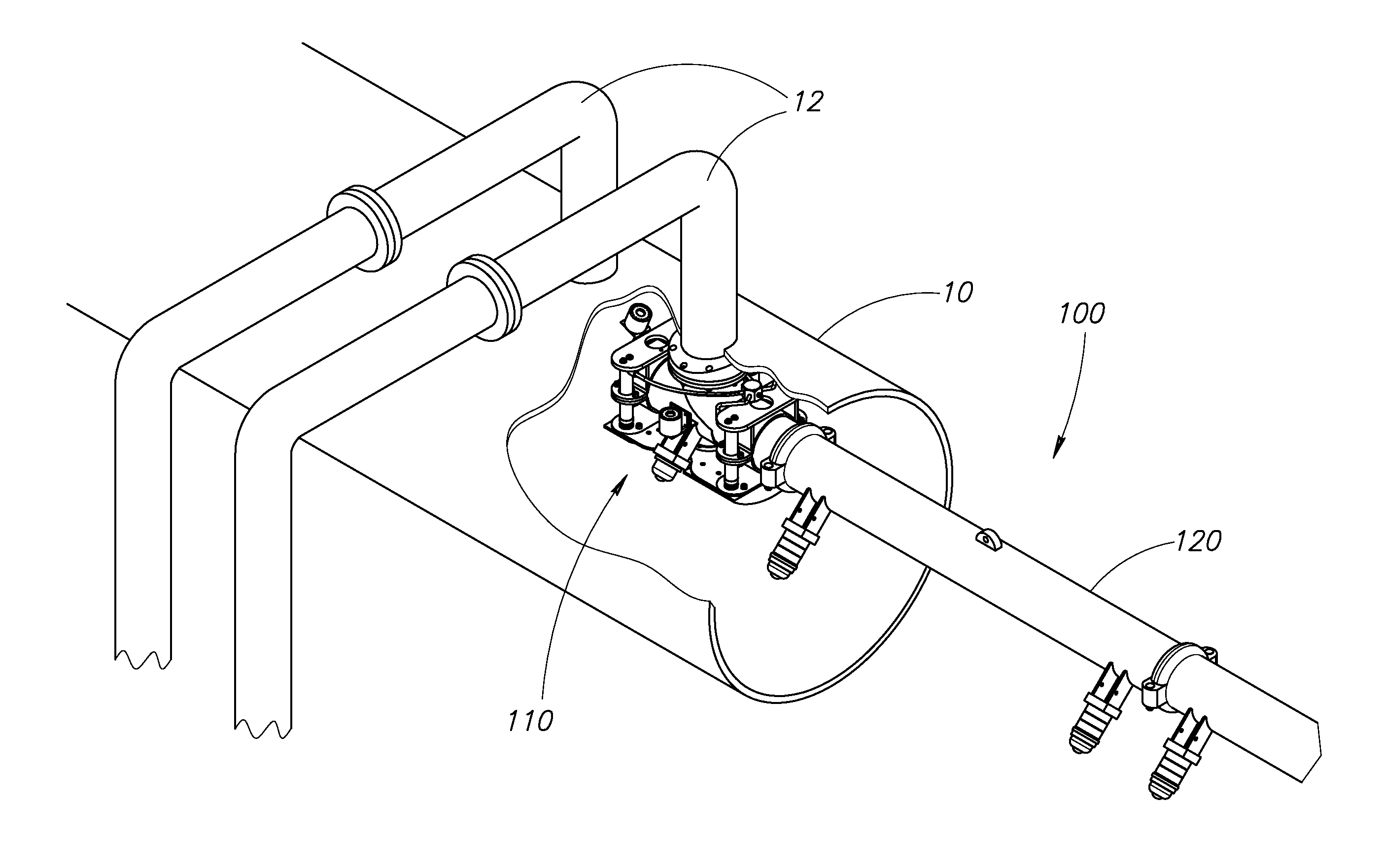
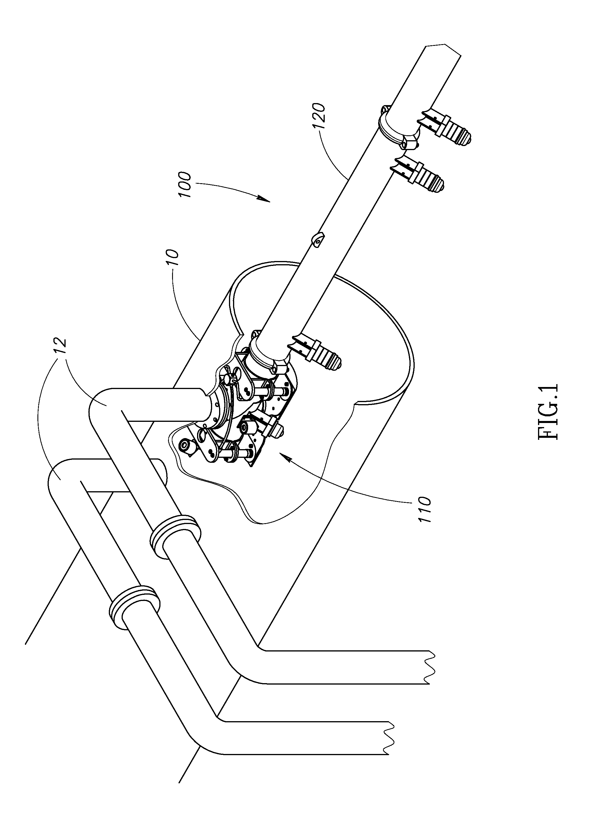
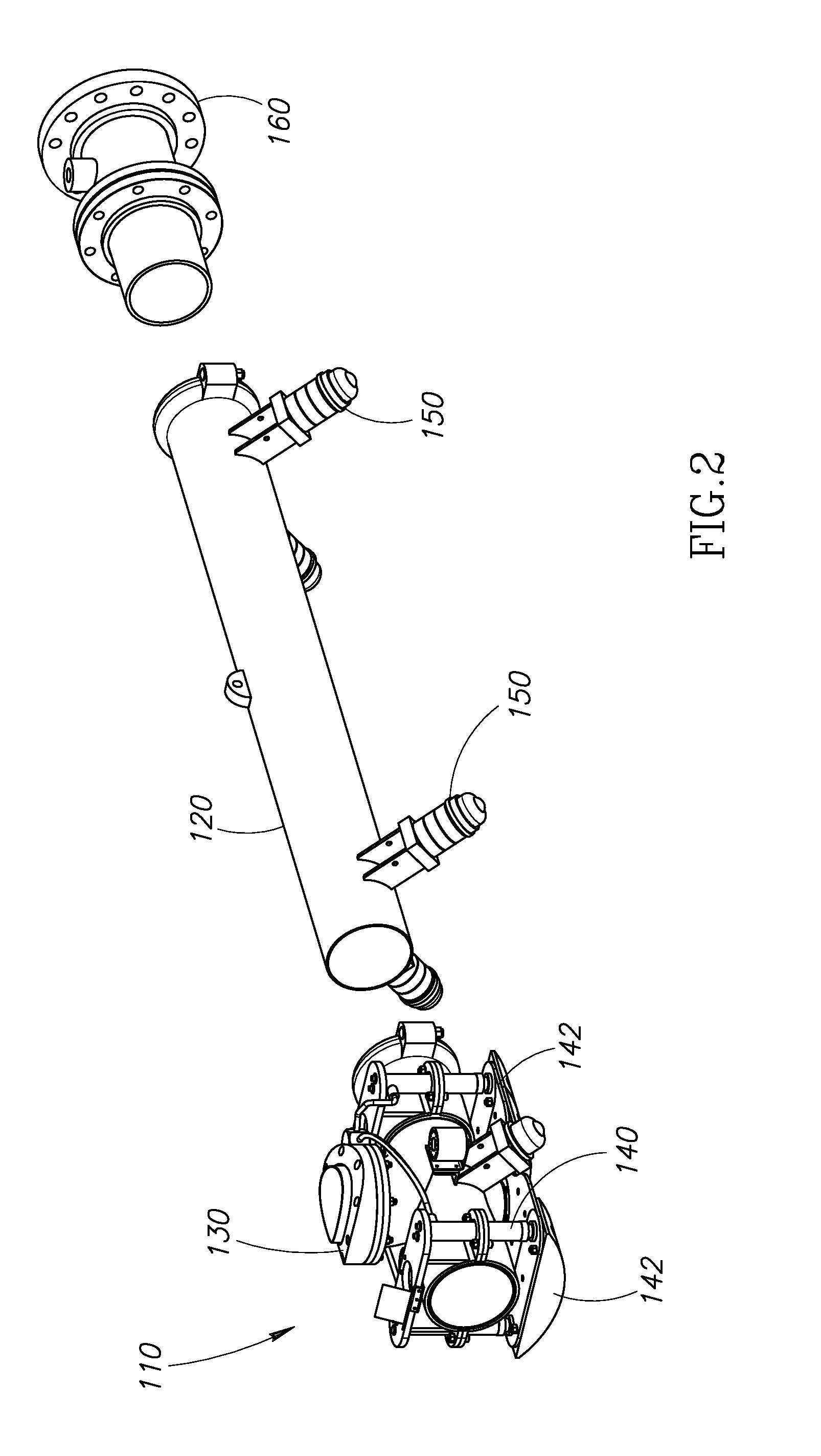
[0013]FIG. 1 illustrates a pipe inspection tool 100 according to embodiments of the present disclosure. The inspection tool 100 includes a head piece 110 and a delivery tube 120. The inspection tool 100 is used to inspect a header pipe 10 having feeder tubes 12 extending from the header pipe 10 at an angle. In general, the feeder tubes 12 have a smaller diameter than the header pipe 10. The systems and methods of the present disclosure can be used in a variety of environments involving pipes of different diameter, some of which are commonly referred to as header pipes and feeder tubes, and some of which are not necessarily referred to as such. For purposes of clarity and brevity, the terms “header pipe” and “feeder tube” are used to refer to a large diameter pipe and a smaller diameter pipe, respectively without loss of generality. The feeder tubes 12 can extend from the header pipe 10 at virtually any angle; in this embodiment, the angle is approximately 90°. The tool 100 can be in...


PUM


Abstract

A pipe inspection system and method for accessing and inspecting a feeder tube extending from a larger header pipe at an angle are disclosed. A pipe inspection tool including a head piece and a delivery tube are positioned within the header pipe and aligned with the feeder tube using cameras or other alignment means. The head piece includes a jack that presses the head piece against the interior surface of the header pipe at the feeder tube to create a sufficient seal to deliver a PIG or another pipe inspection device to the feeder tube.

Description

FIELD OF THE INVENTION[0001]The present disclosure is directed to a pipe inspection system for accessing and inspecting a small diameter pipe that branches from a large diameter pipe at an angle.BACKGROUND OF THE INVENTION[0002]Many industries rely on piping of various diameters to direct fluids, such as air, water, or oil to and from buildings or refineries. Some of this piping is located in environments that are difficult to access for inspection or repair. A common inspection tool is the pipe inspection gauge, or “PIG,” that can be inserted into a pipe and moved along the interior or the pipe and can have a camera or other telemetry tools on board to inspect the pipe. The pipe geometry itself, however, can make inspection difficult even for a sophisticated PIG. Some angles are not negotiable for PIGs. Also, PIGs are not capable of navigating pipe sections of significantly differing diameters. One approach has been to cut into the pipe and deliver PIGs through the cut or to otherw...

Claims


Application Information

Patent Timeline
IPC IPC(8): G01D21/00
CPCG03B37/005F16L55/46
Inventor LOFSTROM, DAN
Owner LOFSTROM DANIEL
Learn More