Driving force transmission apparatus

Inactive Publication Date: 2013-10-24
JTEKT CORP
View PDF4 Cites 4 Cited by
  • Summary
  • Abstract
  • Description
  • Claims
  • Application Information

AI Technical Summary

Benefits of technology

[0016]It is an object of the invention to provide a driving force transmission apparatus configured to keep the oil level of lubrica

Problems solved by technology

On the other hand, if the amount of lubricating oil in the housing is excessively small while the four-wheel-drive vehicle travels in a four-wheel-drive mode, there is a possibility that the clutch plates may be

Method used


Image

  • Driving force transmission apparatus
  • Driving force transmission apparatus
  • Driving force transmission apparatus

Examples


Example

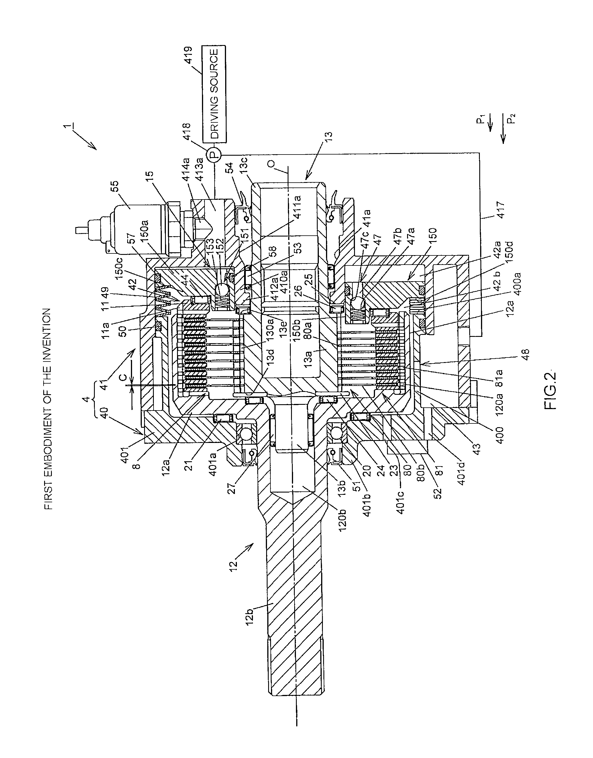
[0087]According to the above-described first embodiment, the following advantageous effects are obtained.

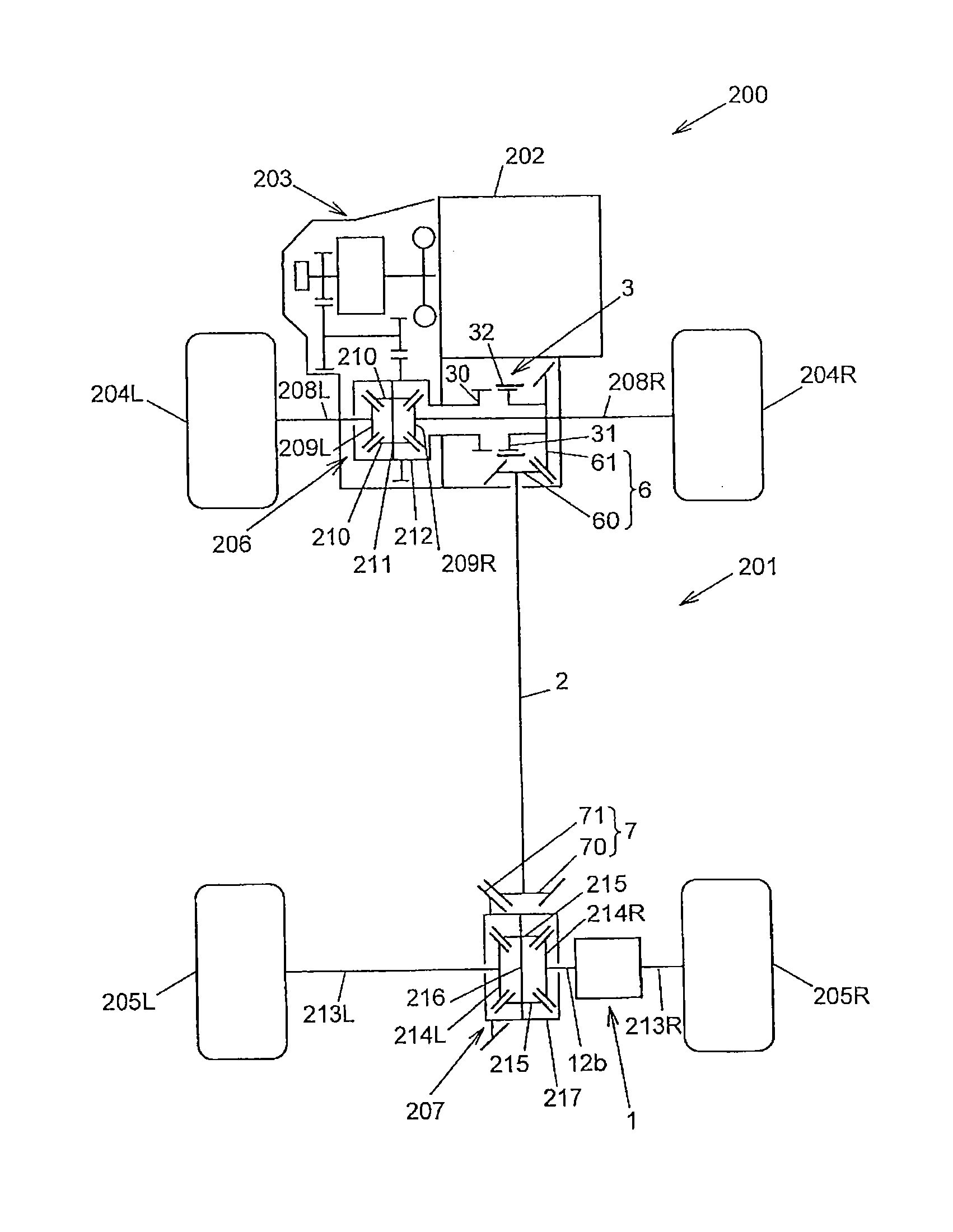
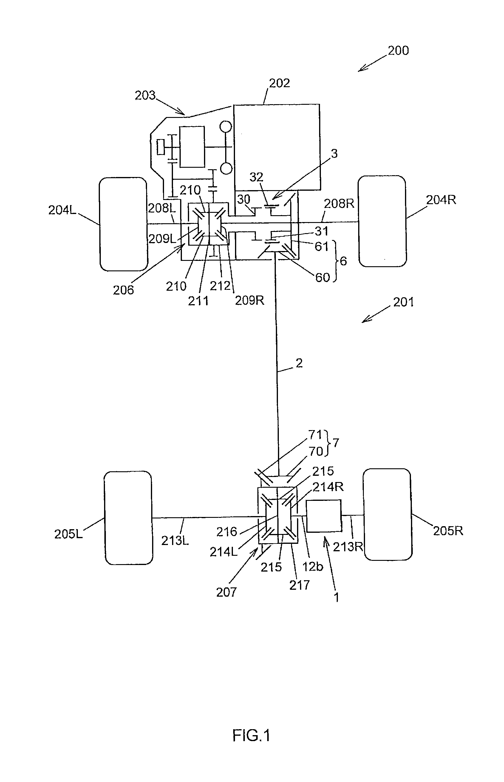
[0088](1) It is possible to keep the oil level of the lubricating oil in the apparatus case 4 (space 42b) at a desired oil level when the four-wheel-drive vehicle 200 travels in the four-wheel-drive mode and in the two-wheel-drive mode. Therefore, it is possible to reduce drag torque, and it is possible to suppress a decrease in the durability of the clutch 8. In this case, connection of the housing 12 with the inner shaft 13 is achieved by applying the first pressing force P1 and the second pressing force P2 to the clutch 8. Therefore, it is possible to increase the clearance between the clutch plates of the clutch 8, and it is possible to further improve the effect of reducing drag torque.

[0089](2) The piston 150 is returned to the initial position by the return spring 49. Therefore, it is possible to drain the lubricating oil to the outside of the apparatus case 4 with the use...

Example

[0093]Next, a driving force transmission apparatus 100 according to a second embodiment of the invention will be described with reference to FIG. 4. FIG. 4 shows the driving force transmission apparatus. In FIG. 4, the components having the same or equivalent functions to those in FIG. 2 are denoted by the same reference numerals as those in FIG. 2, and the detailed description is omitted.

[0094]As shown in FIG. 4, the driving force transmission apparatus 100 according to the second embodiment of the invention differs from the driving force transmission apparatus 1 according to the first embodiment in that, instead of the oil inlet portions 47 arranged inside the apparatus case 4, an oil inlet portion 101 is arranged outside of the apparatus case 4 (outside of the oil supply-side space 42a and the clutch-side space 42b).

[0095]Therefore, the oil inlet portion 101 has an oil flow passage 101a. One end portion of the oil flow passage 101a is connected to the space 42a via a pipe 102, an...


PUM


Abstract

In a driving force transmission apparatus, an oil inlet portion for introducing hydraulic fluid from one of spaces to the other one of the spaces is formed, and an apparatus case has an oil outlet portion for delivering the hydraulic fluid from the other one of the spaces to an outside of the other one of the spaces with an oil delivery capacity lower than an oil introducing capacity of the oil inlet portion. A pressure regulation valve for bringing the oil inlet portion into an open state upon reception of hydraulic pressure higher than or equal to a predetermined pressure from hydraulic fluid is arranged at the oil inlet portion.

Description

INCORPORATION BY REFERENCE[0001]The disclosure of Japanese Patent Application No. 2012-098753 filed on Apr. 24, 2012 including the specification, drawings and abstract, is incorporated herein by reference in its entirety.BACKGROUND OF THE INVENTION[0002]1. Field of the Invention[0003]The invention relates to a driving force transmission apparatus that transmits driving force from an input shaft to an output shaft in, for example, an automobile.[0004]2. Description of the Related Art[0005]There is a conventional driving force transmission apparatus that is mounted in, for example, a four-wheel-drive vehicle and in which a pair of rotary members are coupled to each other by a clutch such that torque is transmittable therebetween (see, for example, Japanese Patent Application Publication No. 2008-121796 (JP 2008-121796 A)).[0006]The driving force transmission apparatus is formed of a first rotary member, a second rotary member, a friction clutch and a pressing force application mechani...

Claims


Application Information

Patent Timeline
IPC IPC(8): F16D25/06
CPCF16D25/06F16D25/082F16D25/123F16D2048/029
Inventor TAKAI, TOMOYOSHITAKUNO, HIROSHISUZUKI, KUNIHIKO
Owner JTEKT CORP
Why Eureka
Try Eureka