
Transfer case

a transfer case and clutch technology, applied in the field of transfer cases, can solve the problems of not being able to realise a highly efficient disconnect system, the need to use a high torque clutch to transfer high torque loads, and the high drag of high torque clutches

Active Publication Date: 2016-04-28
JAGUAR LAND ROVER LTD
View PDF7 Cites 5 Cited by
  • Summary
  • Abstract
  • Description
  • Claims
  • Application Information

AI Technical Summary

Benefits of technology

This patent is about a new gear system that allows for high on-demand torque output using a small clutch. This system reduces drag torque and improves oil expulsion, while also reducing power loss. The use of a smaller clutch also reduces mass, cost, and packaging requirements. The second gear can be coupled to the first input drive means, and the second clutch means can selectively couple the second ring gear to either the second planet carrier or a fixed ground. The first and second planetary gears can be mounted on common pinion pins. Overall, this invention provides improved performance and efficiency in gear systems.

Problems solved by technology

A limitation of known on-demand transfer cases is the need to use a high torque clutch to transfer high torque loads.
However, a high torque clutch typically has a high drag when operating under high delta speeds and it may not be possible to realise a highly efficient disconnect system.
This can prove problematic for motor vehicles requiring a transfer case capable of withstanding high torque loads.
The operation of the differential cannot readily be controlled independently, so it is not possible selectively to engage / disengage the transfer drive means 21.

Method used


Image

  • Transfer case
  • Transfer case
  • Transfer case

Examples


Embodiment Construction

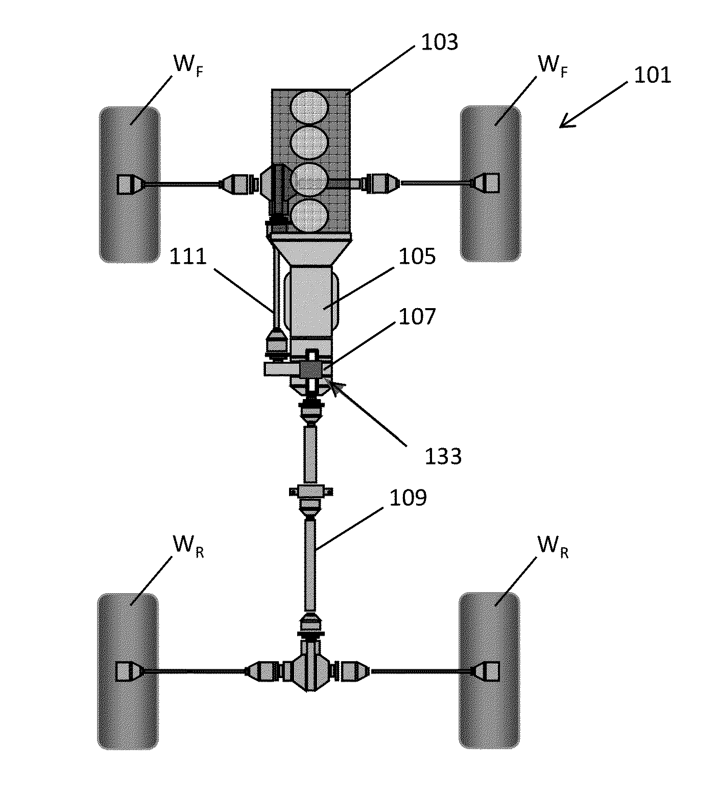
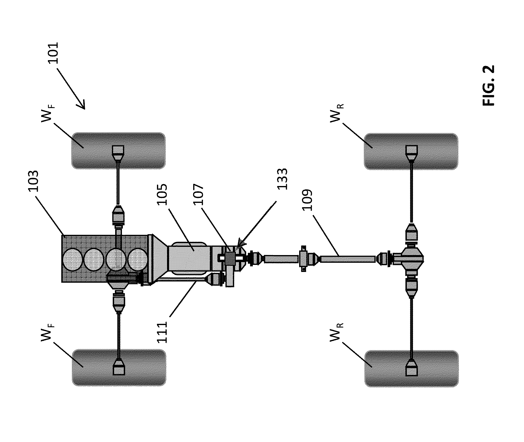
[0051]A schematic representation of a driveline 101 for a four wheel drive vehicle V is shown in FIG. 2. The driveline 101 is connected to an internal combustion engine 103 arranged in a longitudinal (North South) configuration. An output shaft of the internal combustion engine 103 is connected to a gearbox 105 and the output of the gearbox 105 is connected to a transfer case 107 in accordance with an embodiment of the present invention.

[0052]The transfer case 107 is configured to be continuously drivingly coupled to a main drive (propeller) shaft 109 and selectively drivingly coupled to an auxiliary drive (propeller) shaft 111. Thus, the transfer case 107 is an on-demand transfer case operatively configured to continuously transmit torque to the main drive draft 109 and to selectively transmit torque to the auxiliary drive shaft 111. The main drive shaft 109 is adapted to transmit torque to a set of rear wheels WR of the vehicle V; and the auxiliary drive shaft 111 is adapted to tr...


PUM


Abstract

A vehicle transfer case has a first input drive means, a first output drive means and a second output drive means. A first epicyclic gear set is provided in the transfer case. The first epicyclic gear set includes a first sun gear, a plurality of first planetary gears, a first planet carrier and a first ring gear. A first clutch means is configured to control the first epicyclic gear set. The first output drive means is drivingly coupled to the first input drive means; and the first clutch means selectively drivingly couples the second output drive means to the first input drive means.

Description

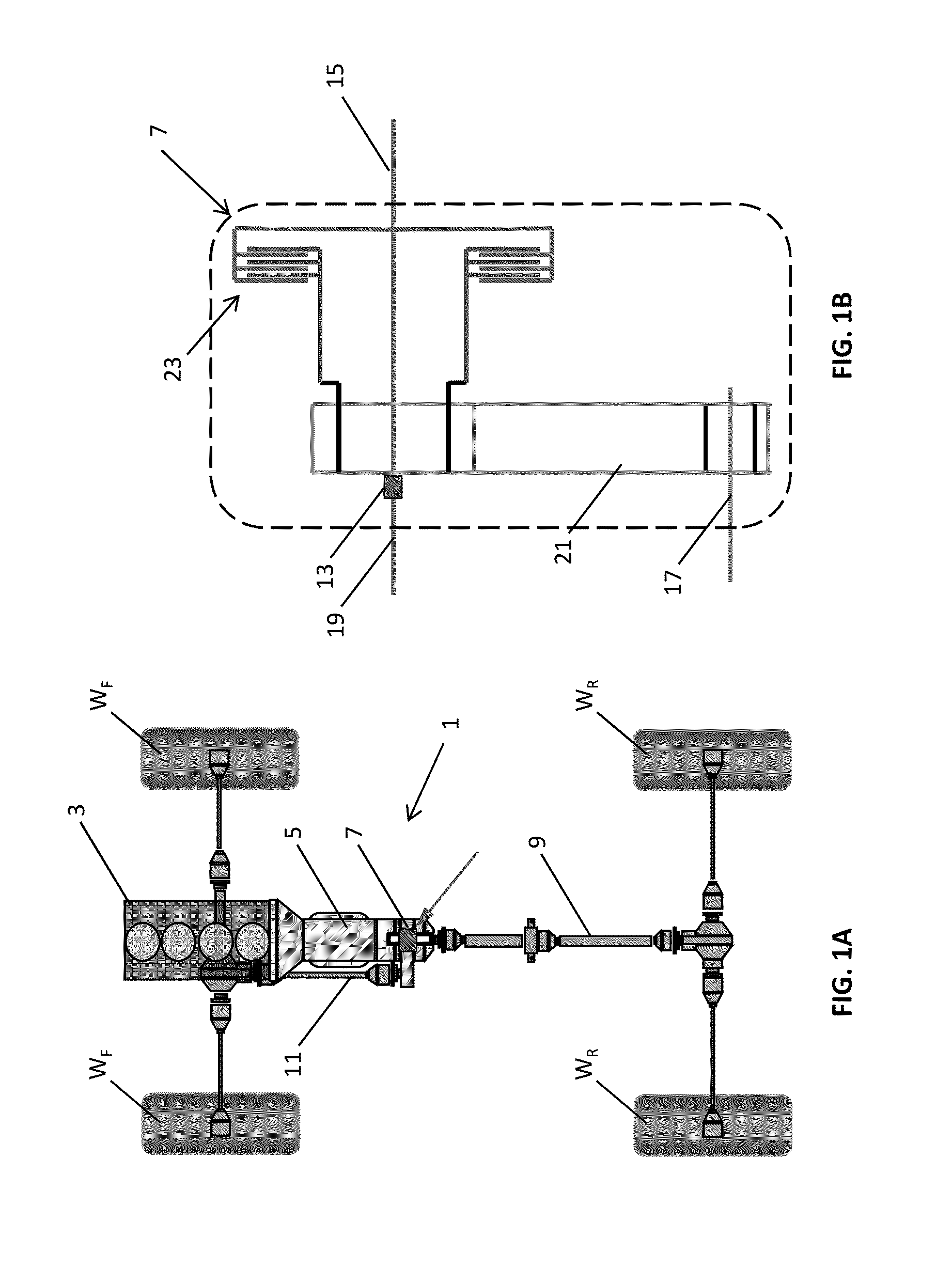
TECHNICAL FIELD[0001]The present disclosure relates to a transfer case. Aspects of the invention relate to a transfer case, to a vehicle driveline and to a vehicle.BACKGROUND[0002]It is known to provide a four wheel drive vehicle with a means of disconnecting two of the driving wheels when the vehicle is driven on less challenging terrain, for example “on road”. A schematic representation of a driveline 1 for such a vehicle is shown in FIG. 1A. The driveline 1 is connected to an internal combustion engine 3 arranged in a longitudinal (North South) configuration. An output shaft of the internal combustion engine 3 is connected to a gearbox 5. The disconnect means is in the form of a transfer case 7 configured to split torque between a main drive (propeller) shaft 9 and an auxiliary drive (propeller) shaft 11. The main drive shaft 9 transmits torque to a pair of rear wheels WR; and the auxiliary drive shaft 11 transmits torque to a pair of front wheels WF. The transfer case 7 is opera...

Claims


Application Information

Patent Timeline
IPC IPC(8): F16H48/10F16H37/08B60K17/346F16H48/22
CPCF16H48/10F16H48/22F16H2048/106B60K17/346F16H2048/104F16H37/0806F16H3/54F16H2200/0034F16H2200/2005F16H2200/2035
Inventor OSBORN, RUSSELL
Owner JAGUAR LAND ROVER LTD
Learn More