Device for damping vibration of transmission

A damper and transmission technology, applied in the field of vibration devices, can solve problems such as uneven shifting operation, increase of input shaft resistance torque, and adverse effects on operation synchronization, so as to increase the degree of freedom, eliminate vibration and vibration noise, and prevent Effect of excessive increase in overall length

Inactive Publication Date: 2016-10-05
HYUNDAI MOTOR CO LTD
View PDF0 Cites 5 Cited by
  • Summary
  • Abstract
  • Description
  • Claims
  • Application Information

AI Technical Summary

Problems solved by technology

[0003] However, in a configuration in which the inertial disc is fixedly mounted to the input shaft, the inertial force of the input shaft itself remains high, resulting in an increase in the resistance torque of the input shaft at the time of gear shifting, which adversely affects the synchronicity of operation, and Provides rough shift operation
[0004] In addition, such inertial disks have space limitations for installation in existing transmission housings

Method used


Image

  • Device for damping vibration of transmission
  • Device for damping vibration of transmission

Examples


Embodiment Construction

[0021] Hereinafter, an exemplary embodiment of a device for damping vibration of a rotating shaft of a transmission (ie, a vibration damper) will be described with reference to the accompanying drawings.

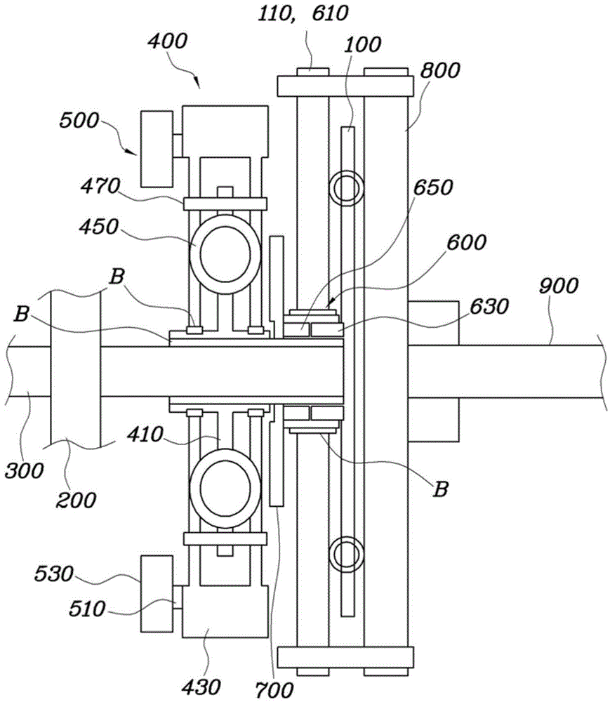
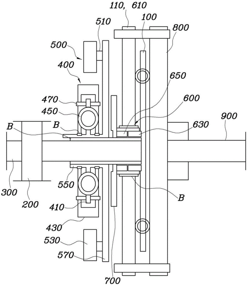
[0022] figure 1 is a view of a series connection of vibration damping devices of a transmission rotary shaft according to an embodiment of the present invention, figure 2 is a view of the parallel connection of the vibration damping device.

[0023] The device for damping vibration of the transmission rotating shaft (ie, the vibration damping device) includes: an input shaft damper (ISD) 400 rotatably disposed around the transmission rotating shaft 300 between the clutch 100 and the transmission housing 200 ; a centrifugal pendulum assembly (CPA) 500, which is rotatably connected to the ISD to damp the pulsation of the ISD; and a bi-directional actuator 600, which is disposed between the input shaft damper 400 and the clutch 100, for 400 and clutch 100 apply force bi-dire...


PUM


Abstract

The present invention discloses a device for damping vibration of a transmission. The device for damping vibration of a rotary shaft of a transmission comprises an input shaft damper rotatably provided between a clutch and a transmission housing around an input shaft of the transmission; a centrifugal pendulum assembly rotatably connected to the input shaft damper to damp pulsation of the input shaft damper; and a bidirectional actuator provided between the input shaft damper and the clutch for bidirectionally applying force to the input shaft damper and the clutch so as to allow simultaneous bidirectional linear motions.

Description

technical field [0001] The present invention basically relates to a technique of variably providing inertial force to a rotary shaft of a manual transmission of a vehicle. More specifically, the present invention relates to a device for damping vibration of a rotating shaft of a transmission, which damps vibration of a rotating shaft of a transmission by providing an inertial force to an input shaft of the transmission to avoid resonance within a specific frequency range, Thereby reducing the vibration of the transmission and the noise generated due to the vibration. Background technique [0002] As disclosed in related art patent documents, by providing an inertial plate to a transmission, vibration and vibration noise of the transmission due to resonance in a specific frequency band can be avoided without using a dual mass flywheel (DMF) or the like. [0003] However, in a configuration in which the inertial disc is fixedly mounted to the input shaft, the inertial force o...

Claims


Application Information

Patent Timeline
Patent Type & Authority Applications(China)
IPC IPC(8): F16H57/028
CPCF16D25/082F16D3/12F16D25/083F16D2300/22F16F15/145
Inventor 黄载雄陈用郁吴浣守
Owner HYUNDAI MOTOR CO LTD
Why Eureka
Try Eureka