Power generating apparatus

a technology of power generating apparatus and drive shaft, which is applied in the direction of mechanical equipment, mechanical energy handling, machines/engines, etc., can solve the problems of affecting the normal rotation of the drive shaft of the generator

Inactive Publication Date: 2013-10-24
JTEKT CORP
View PDF4 Cites 17 Cited by
  • Summary
  • Abstract
  • Description
  • Claims
  • Application Information

AI Technical Summary

Benefits of technology

[0009]It is an object of the invention to provide a power generating apparatus configured such that occurrence of smearing at a roller bearing

Problems solved by technology

As a result, sliding friction resistance, and the like, between rollers of the roller bearing and a cage that retains the rollers becomes larger than rolling friction resistanc

Method used


Image

  • Power generating apparatus
  • Power generating apparatus
  • Power generating apparatus

Examples


Embodiment Construction

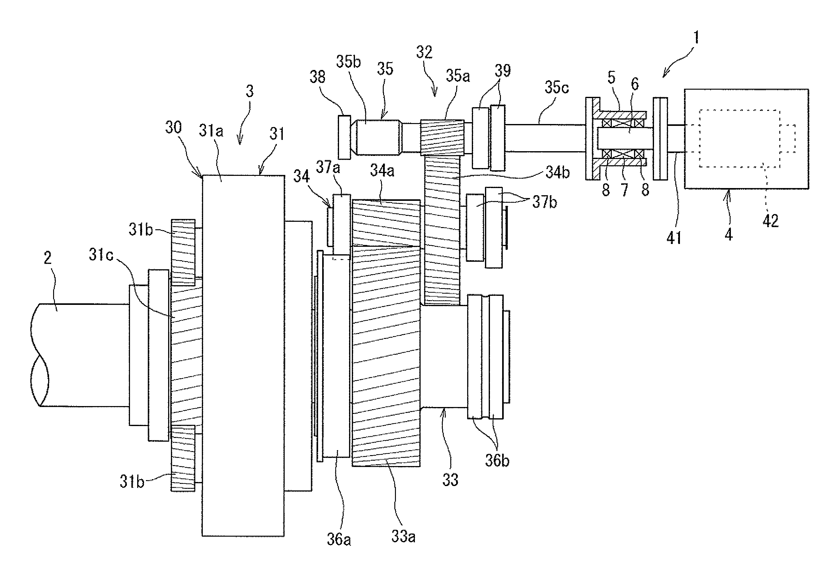
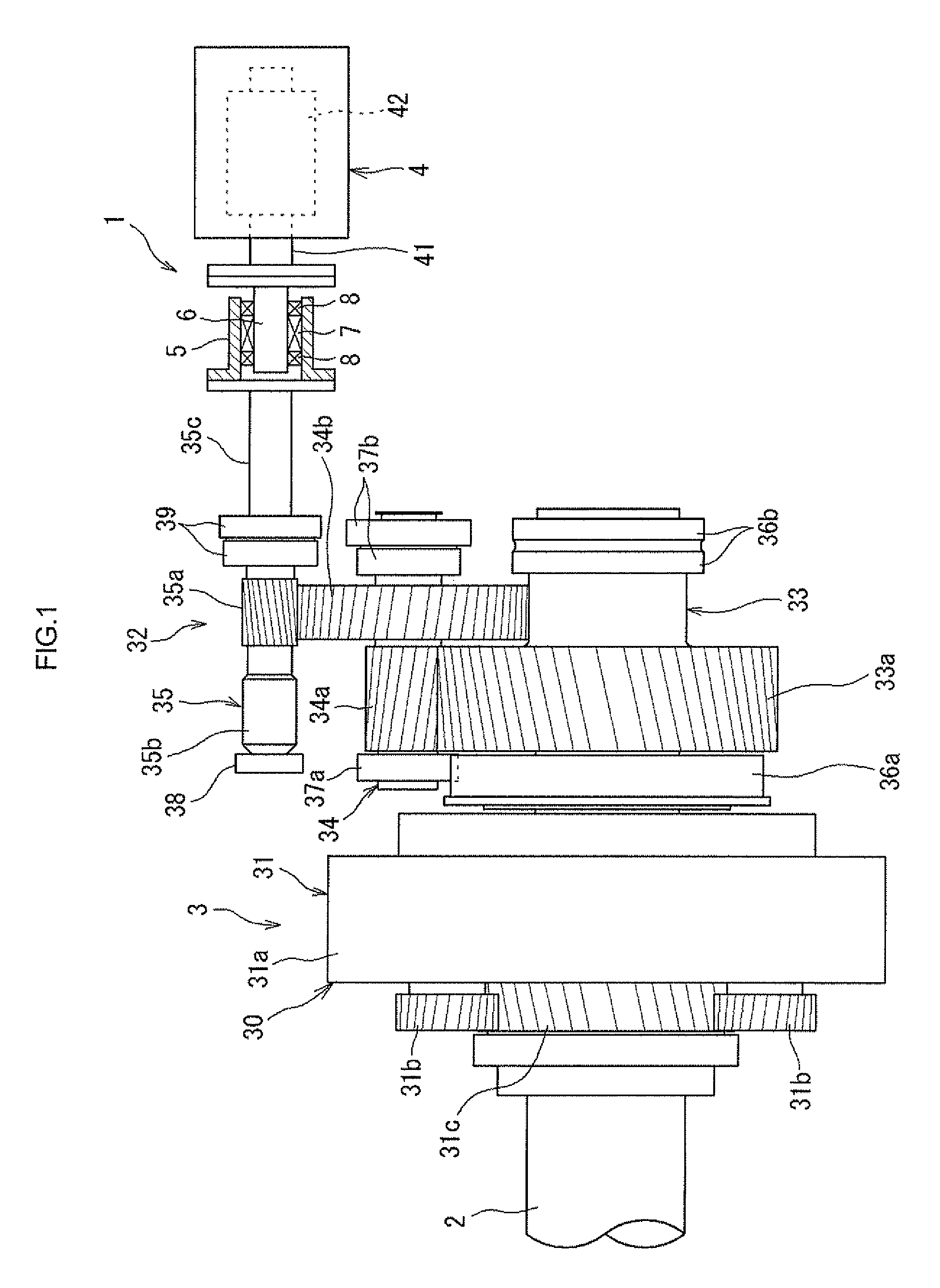
[0022]Hereinafter, embodiments of the invention will be described with reference to the accompanying drawings. FIG. 1 is a schematic side view that shows a wind power generator 1 according to an embodiment of the invention. The wind power generator (power generating apparatus) 1 includes a main shaft 2, a speed increaser 3 and a generator 4 coupled to the speed increaser 3. The main shaft 2 rotates upon reception of wind force (external force). The speed increaser 3 is coupled to the main shaft 2. The generator 4 is coupled to the speed increaser 3. The generator 4 is driven while the speed of rotation transmitted from the main shaft 2 is increased by the speed increaser 3.

[0023]For example, blades (not shown) are coupled to the distal end portion of the main shaft 2 so as to be rotatable together with the main shaft 2. When the blades receive wind force, the blades rotate together with the main shaft 2. The generator 4 includes, for example, a drive shaft 41, a rotor 42 and a stato...


PUM


Abstract

A wind power generator includes: an input rotor provided so as to be rotatable together with an output shaft of a speed increaser; an output rotor provided so as to be rotatable together with a drive shaft of a generator; and a one-way clutch arranged between the input and output rotors. The one-way clutch connects the input rotor to the output rotor such that the input rotor and the output rotor are rotatable together with each other when a rotation speed of the input rotor exceeds a rotation speed of the output rotor, and that disconnects the input rotor from the output rotor when the rotation speed of the input rotor falls below the rotation speed of the output rotor. The one-way clutch has a rotation speed limiter that disconnects the input rotor from the output rotor when the rotation speed of the output shaft exceeds a predetermined value.

Description

INCORPORATION BY REFERENCE[0001]The disclosure of Japanese Patent Applications No. 2012-095612 filed on Apr. 19, 2012 and 2012-231728 filed on Oct. 19, 2012 including the specification, drawings and abstract, is incorporated herein by reference in its entirety.BACKGROUND OF THE INVENTION[0002]1. Field of the Invention[0003]The invention relates to a power generating apparatus in which the speed of rotation caused by external force and transmitted from a main shaft is increased by a speed increaser to drive a generator.[0004]2. Description of Related Art[0005]In some conventional wind power generators, a main shaft connected to blades is rotated upon reception of wind force and the speed of rotation transmitted from the main shaft is increased by a speed increaser to drive a generator. As shown in FIG. 9, a speed increaser 202 includes a planetary gear mechanism 203, a high-speed gear mechanism 204 and an output shaft 205. The planetary gear mechanism 203 receives rotation from a mai...

Claims


Application Information

Patent Timeline
IPC IPC(8): H02K7/08H02K7/108
CPCH02K7/08H02K7/108F16D41/067F05B2260/4023F16D43/14F03D15/00F03D15/10F03D80/70Y02E10/72
Inventor FUJIWARA, HIDEKI
Owner JTEKT CORP
Why Eureka
Try Eureka