Method of detecting battery degradation level

a battery and degradation level technology, applied in the field of detecting battery degradation level, can solve the problems of battery not being able to operate in a fully-charged state or fully-discharged state in a solar cell power storage application, unable to detect full-charge capacity by simply integrating the discharge current, and unable to charge by regenerative braking, so as to ensure the protection of battery life, prolong the life, and minimize degradation. the effect of degradation

Inactive Publication Date: 2013-10-24
SANYO ELECTRIC CO LTD
View PDF80 Cites 49 Cited by
  • Summary
  • Abstract
  • Description
  • Claims
  • Application Information

AI Technical Summary

Benefits of technology

[0021]The method of detecting battery degradation level of the present invention can be used in an application that controls battery 1 charging and discharging within a pre-set residual capacity (SOC [%]) range. In this method of detecting degradation level, full-charge capacity is accurately detected from the battery degradation level, and with the detected full-charge capacity, battery operation can be controlled within a fixed residual capacity range. As a result, this method has the characteristic that battery over-charging and over-discharging can be reliably prevented allowing extended lifetime.
[0022]The method of detecting battery degradation level of the present invention can be applied to a battery 1 that supplies power to a motor 12 to drive a vehicle. In this method of detecting degradation level, full-charge capacity of a battery that supplies power to a motor is detected from the degradation level, and from the detected full-cha

Problems solved by technology

However, full-charge capacity determination by these methods requires the battery either to be charged from a fully discharged state to a fully-charged state or to be discharged from a fully-charged state to a completely discharged state.
For a battery used in an operating environment that does not completely discharge or fully-charge the battery, full-charge capacity cannot be detected by simply integrating the discharge current or charging current.
For example, in a hybrid vehicle application, the vehicle cannot be driven by the battery if it is completely discharged, and the battery cannot be charged by regenerative braking if it is fully-charged.
Consequently, it can be d

Method used


Image

  • Method of detecting battery degradation level
  • Method of detecting battery degradation level
  • Method of detecting battery degradation level

Examples


Embodiment Construction

[0034]The following describes embodiments of the present invention based on the figures. However, the following embodiments are merely specific examples of a method of detecting battery degradation level representative of the technology associated with the present invention, and the method of detecting battery degradation level of the present invention is not limited to the embodiments described below. Further, components cited in the claims are in no way limited to the components indicated in the embodiments.

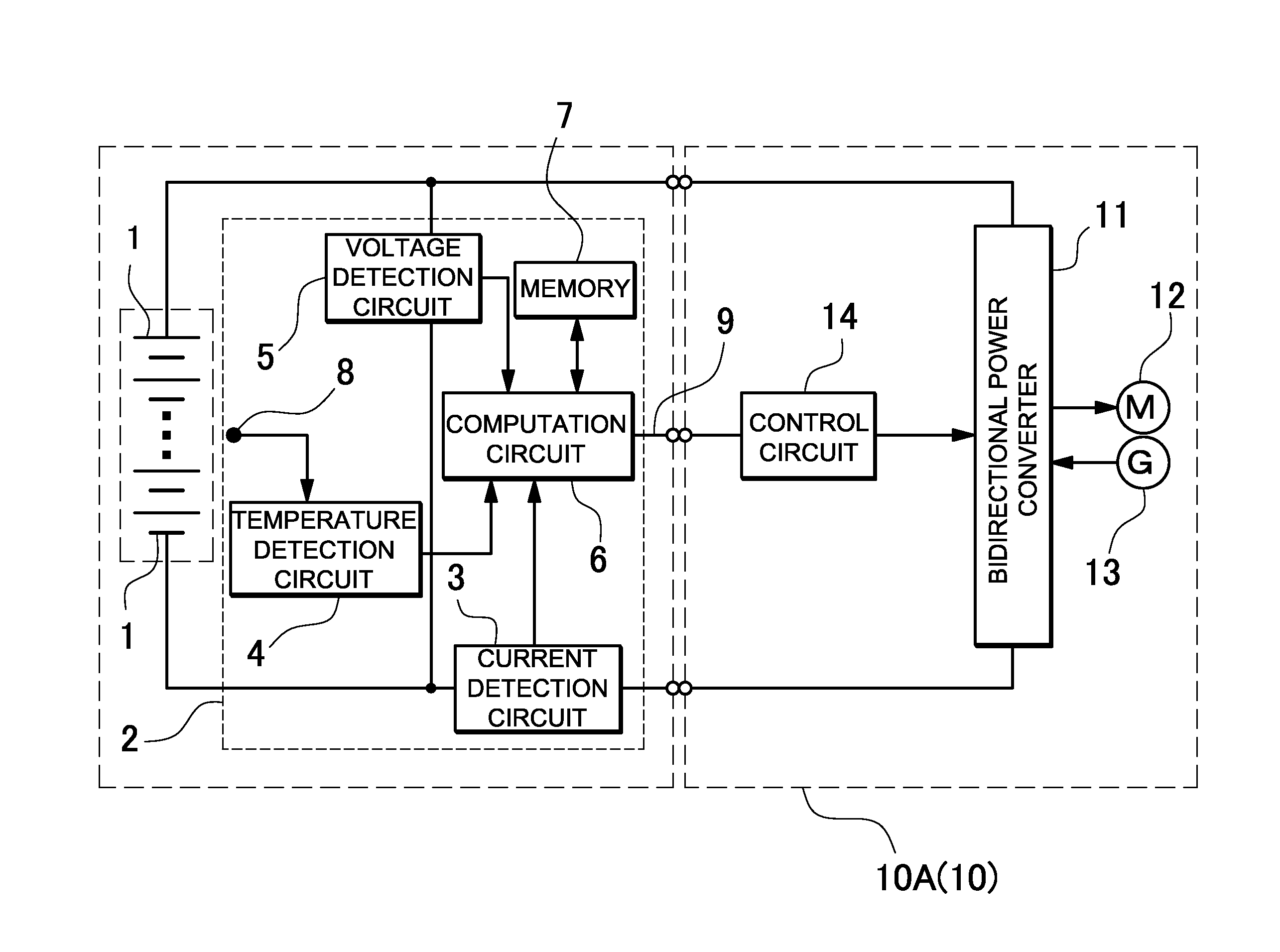
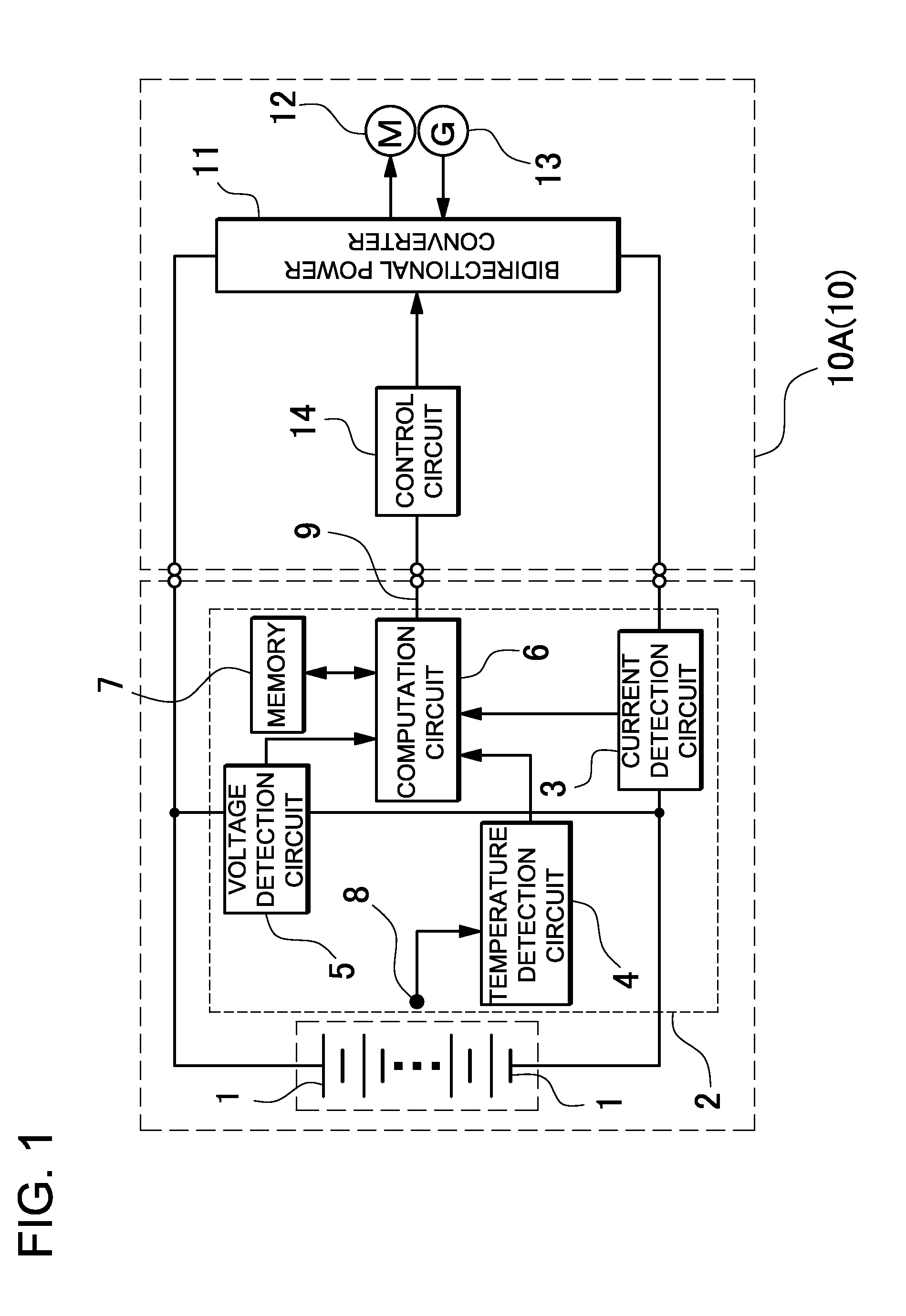
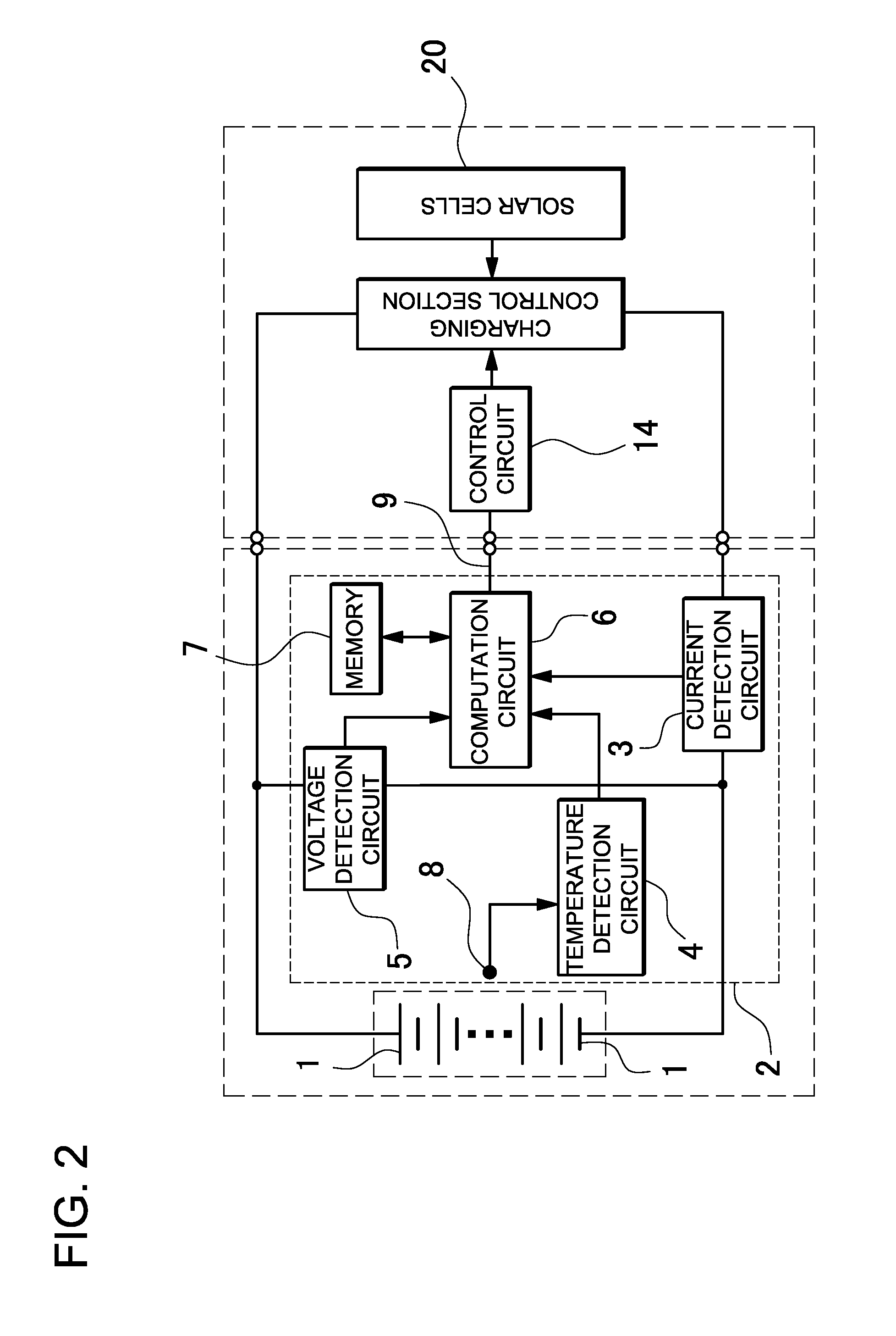
[0035]FIGS. 1 and 2 are block diagrams of power source apparatus that use the method of detecting battery degradation level of the present invention. FIG. 1 shows a block diagram for determining the degradation level of a battery 1 installed on-board a hybrid vehicle 10A, and FIG. 2 shows a block diagram for determining the degradation level of a battery 1 charged by solar cells 20. However, the present invention is not limited to detecting degradation level of a battery applie...


PUM


Abstract

The method of detecting battery degradation level detects the change in residual capacity (ΔSOC) for one charging period or one discharging period of a battery 1 being charged and discharged. Weighting factors that establish degradation level according to the value of ΔSOC are pre-stored in memory, and based on the stored data; weighting factors are determined from the detected ΔSOC to determine the battery 1 degradation level from the weighting factors.

Description

BACKGROUND OF THE INVENTION[0001]1. Field of the Invention[0002]The present invention relates to a method of detecting battery degradation level, and in particular to a method of detecting degradation level optimally suited for a battery used in a power source apparatus that drives an electric-powered vehicle or a battery used in a solar cell power storage unit.[0003]2. Description of the Related Art[0004]A rechargeable battery degrades with charge-discharge cycle repetitions and the capacity to which it can be charged decreases. Since degradation increases due to over-charging and over-discharging, degradation can be reduced and battery lifetime extended by preventing over-charging and over-discharging, and by limiting charging and discharging operation in regions close to over-charging and over-discharging. Further, degradation can be restrained and lifetime extended by reducing the allowable current, lowering the charging voltage, or narrowing the operating temperature range as d...

Claims


Application Information

Patent Timeline
IPC IPC(8): H02J7/00
CPCH02J7/00B60L3/0046B60L8/003H01M10/48H01M10/465H01M10/486B60L2240/545B60L2240/547B60L2240/549H01M2220/10H01M2220/20Y02T10/7072G01R31/367G01R31/392B60L50/51B60L58/16B60L58/15H02J7/0048B60L58/13Y02T10/70Y02E60/10Y02T90/14
Inventor MAEDA, REIZO
Owner SANYO ELECTRIC CO LTD
Why Eureka
Try Eureka