Antenna arrangement

Active Publication Date: 2013-10-24
CELLMAX TECH AB
View PDF0 Cites 1 Cited by
  • Summary
  • Abstract
  • Description
  • Claims
  • Application Information

AI Technical Summary

Benefits of technology

[0009]The phase shift is achieved by moving a dielectric part that is located between the inner conductor and the outer conductor of the coaxial lines. It is a known physical property that introducing a material with higher permittivity than air in a transmission

Problems solved by technology

Base station antennas with variable tilt angles using adjustable phase shifters already exist and are widely deployed, but their performance has so far been limited by the loss introduced in the int

Method used


Image

  • Antenna arrangement
  • Antenna arrangement
  • Antenna arrangement

Examples


Embodiment Construction

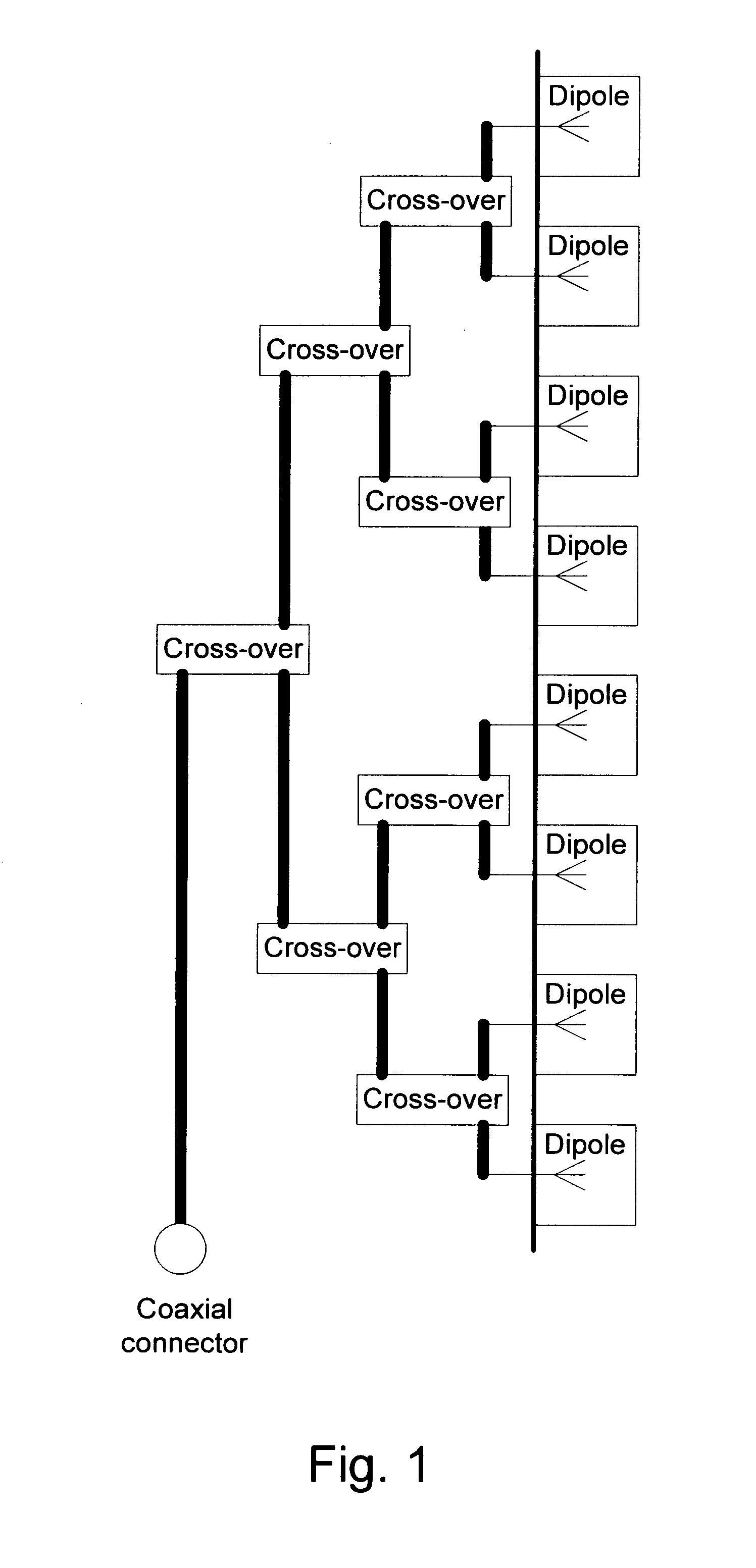
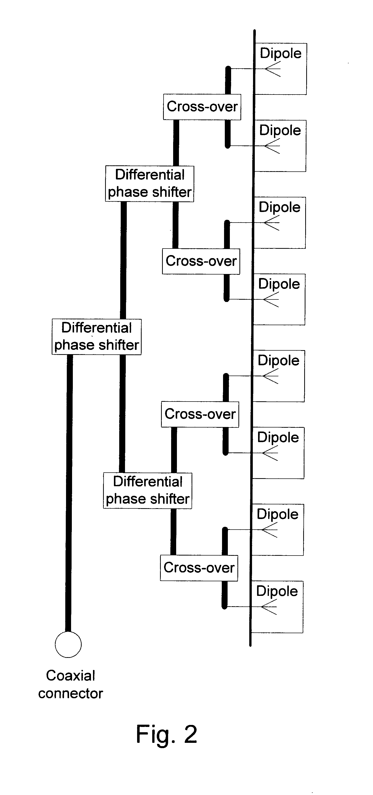
[0020]One embodiment of a differential phase shifter according to the present invention is shown in FIG. 4. The differential phase shifter comprises one input coaxial line 1, a first output coaxial line 2 and a second output coaxial line 3, both output coaxial lines having the same length in this example. An extruded metal profile 8 is used as outer conductor for all coaxial lines, in the same way as described in WO 2005 / 101566 A1, now U.S. Pat. No. 7,619,580. The input coaxial line inner conductor 4 is connected to the first output coaxial line inner conductor 5 and the second output inner conductor 6 via a crossover 7 covered by a conductive lid 10. This differential phase shifter can typically be used in an antenna having e.g. 4, 8 or 16 radiators, one example being shown in FIG. 2. The differential phase shifter in FIG. 4 can also be used in other configurations, e.g. as shown in FIG. 3.

[0021]A dielectric part 9 partly fills the space between the inner and outer conductors of th...


PUM


Abstract

Antenna arrangement for a multi-radiator base station antenna, the antenna having a feeding network based on air filled coaxial lines (1, 2, 3), wherein each coaxial line comprises an outer conductor (8) and an inner conductor (4, 5, 6), wherein an adjustable differential phase shifter including a dielectric part (9) is arranged in the antenna and said dielectric part being movable longitudinally in relation to at least one coaxial line 1, 2, 3).

Description

BACKGROUND OF THE INVENTION[0001]The present invention relates to an antenna arrangement for a multi-radiator base station antenna, the antenna having a feeding network based on air filled coaxial lines, wherein the coaxial lines preferably are an integrated part of the antenna reflector. The invention especially relates to such an antenna having a variable electrical elevation tilt angle. Electrical elevation tilt angle is henceforth termed tilt angle.[0002]Antennas in telecommunication systems such as cellular networks today typically use multi-radiator structures. Such antennas make use of an internal feeding network that distributes the signal from a common coaxial connector to the radiators when the antenna is transmitting and in the opposite direction when the antenna is receiving. Typically the radiators are positioned in a vertical column. This arrangement reduces the elevation beam width of the antenna and by that increases the antenna gain. The antenna tilt angle is determ...

Claims


Application Information

Patent Timeline
IPC IPC(8): H01Q21/00
CPCH01Q21/0006H01P1/182H01P1/183H01P5/026H01P5/183H01Q1/246H01Q3/32H01Q9/16H01Q21/0037H01Q21/08
Inventor JONSSON, STEFANKARLSSON, DAN
Owner CELLMAX TECH AB
Why Eureka
Try Eureka