Antenna feeding network comprising at least one holding element

Active Publication Date: 2019-02-21
CELLMAX TECH AB
View PDF5 Cites 1 Cited by
  • Summary
  • Abstract
  • Description
  • Claims
  • Application Information

AI Technical Summary

Benefits of technology

The present invention provides an improved antenna feeding network that overcomes disadvantages of prior art. It uses insulating or dielectric holding elements in openings to hold inner conductors in position, making it easier to connect them. The holding element also helps improve impedance matching and can be used in a splitter / combiner to adjust the phase of signals feeding radiators. The invention simplifies the antenna feeding network and reduces the number of parts needed.

Problems solved by technology

It is however desirable to avoid or minimize openings in general in the outer conductors since openings, and large openings in particular, may result in reduced mechanical stability of the antenna, and may also influence the impedance properties negatively in the antenna feeding network, and may also result in unwanted radiation from the feeding network.
Such unwanted radiation may reduce the antenna performance in terms of e.g. back- or sidelobe suppression.
Openings in the outer conductor on the front side of the reflector may degrade antenna performance more than openings in the back side of the reflector.

Method used


Image

  • Antenna feeding network comprising at least one holding element
  • Antenna feeding network comprising at least one holding element
  • Antenna feeding network comprising at least one holding element

Examples


Embodiment Construction

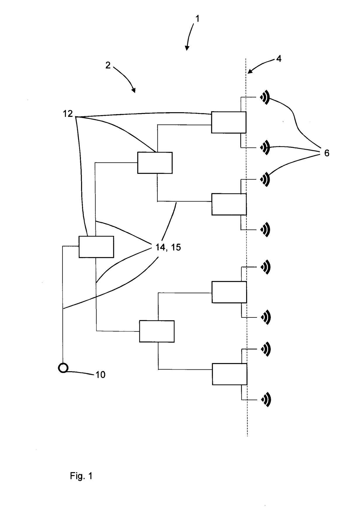
[0039]FIG. 1 schematically illustrates an antenna arrangement 1 comprising an antenna feeding network 2, an electrically conductive reflector 4, which is shown schematically in FIG. 1, and a plurality of radiating elements 6. The radiating elements 6 may be dipoles.

[0040]The antenna feeding network 2 connects a coaxial connector 10 to the plurality of radiating elements 6 via a plurality of lines 14, 15, which may be coaxial lines, which are schematically illustrated in FIG. 1. The signal to / from the connector 10 is split / combined using, in this example, three stages of splitters / combiners 12.

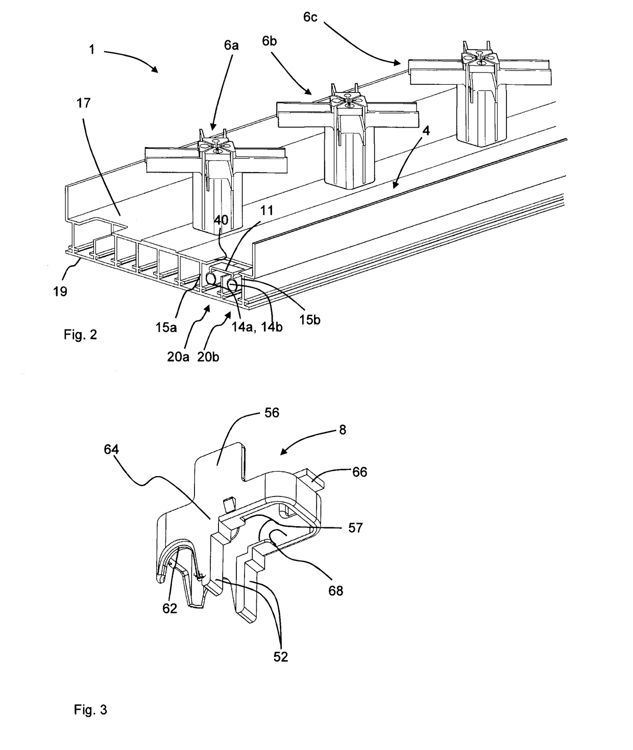
[0041]Turning now to FIG. 2, which illustrates a multi-radiator antenna 1 in a perspective view, the antenna 1 comprises the electrically conductive reflector 4 and radiating elements 6a-c.

[0042]The electrically conductive reflector 4 comprises a front side 17, where the radiating elements 6a-c are mounted and a back side 19.

[0043]FIG. 2 shows a first coaxial line 20a which comprises a first c...


PUM


Abstract

An antenna feeding network for a multi radiator antenna is provided. The antenna feeding network comprises at least one coaxial line. Each coaxial line comprises a central inner conductor and an elongated outer conductor surrounding the central inner conductor, wherein at least one of the outer conductors of the coaxial lines is provided with an opening, wherein the antenna feeding network further comprises at least one nonconductive holding element configured to be placed in the opening. The holding element is configured to hold at least one of the inner conductors in position. The invention further relates to a multi radiator antenna comprising such an antenna feeding network, and to a method for providing an electrical connection in such an antenna feeding network.

Description

TECHNICAL FIELD[0001]The invention relates to the field of antenna feeding networks for multi-radiator antennas, which feeding network comprises at least two coaxial lines.BACKGROUND OF THE INVENTION[0002]Multi-radiator antennas are frequently used in for example cellular networks. Such multi-radiator antennas comprise a number of radiating antenna elements for example in the form of dipoles for sending or receiving signals, an antenna feeding network and an electrically conductive reflector. The antenna feeding network distributes the signal from a common coaxial connector to the radiators when the antenna is transmitting and combines the signals from the radiators and feeds them to the coaxial connector when receiving. A possible implementation of such a feeding network is shown in FIG. 1.[0003]In such a network, if the splitters / combiners consist of just one junction between 3 different 50 ohm lines, impedance match would not be maintained, and the impedance seen from each port w...

Claims


Application Information

Patent Timeline
IPC IPC(8): H01Q21/08H01Q15/14H01Q21/00H01P3/06
CPCH01Q21/08H01Q15/14H01Q21/0006H01P3/06H01R9/0503H01R2201/02H01Q1/246H01Q3/32H01Q21/26H01P5/026H01P1/183H01P5/183H01Q3/30H01Q21/0025H01R9/16H01R24/38
Inventor YMAN, NICLAS J.JONSSON, STEFANKARLSSON, DANNORDSTROM, ANDREAS
Owner CELLMAX TECH AB
Why Eureka
Try Eureka