Lens barrel and lens assembly

a technology of lens barrel and lens assembly, which is applied in the direction of mountings, instruments, optics, etc., can solve the problem that the lens is apt to move to the side without caulking portion readily caused by eccentricity

Active Publication Date: 2013-10-24
OLYMPUS CORP
View PDF1 Cites 36 Cited by
  • Summary
  • Abstract
  • Description
  • Claims
  • Application Information

AI Technical Summary

Benefits of technology

[0007]Additionally, in a lens assembly that requires high precision, it is well known to provide a caulking portion at the whole periphery of a lens outer edge to firmly fix the lens so that the lens is prevented from moving in the range of a gap from a lens insertion frame portion due to vibration or the like. In recent years, particularly, demands for a larger number of pixels or size reduction of a camera or the like have become stronger. In order to achieve these demands, a higher precision of the fixing precision between the lens and the lens frame is required. Moreover, in order to achieve size reduction and effectively utilize barrel space, a lens having cutouts, such as a D-cut shape, is often used.

Problems solved by technology

However, if this structure is given, eccentricity in which the lens is apt to move to the side with no caulking portion is readily caused due to a pressing force that acts through the caulking portion during heat caulking.

Method used


Image

  • Lens barrel and lens assembly
  • Lens barrel and lens assembly
  • Lens barrel and lens assembly

Examples


first modified example

[0121]Next, a first modified example of the present embodiment will be described.

[0122]FIG. 4A is a schematic plan view showing the configuration of a lens assembly related to the first modified example of the embodiment of the present invention. FIG. 4B and FIG. 4C are a C-C cross-sectional view and a D-D cross-sectional view in FIG. 4A, respectively. FIG. 5A is a schematic plan view showing the configuration of a lens barrel related to the first modified example of the embodiment of the present invention. FIG. 5B is a C′-C′ cross-sectional view of FIG. 5A. FIG. 5C is a D′-D′ cross-sectional view of FIG. 5A.

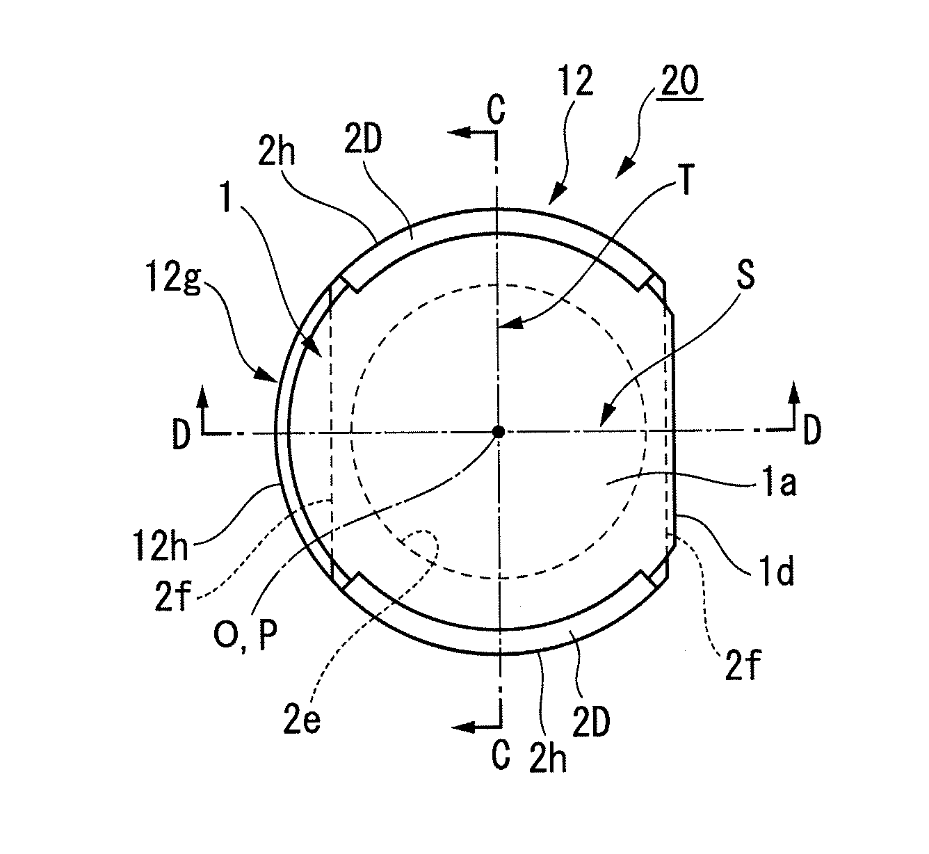
[0123]The lens assembly 20 of the present modified example, as shown in FIGS. 4A, 4B, and 4C, includes a lens barrel 12 instead of a lens barrel 2 in the lens assembly 10 of the above embodiment.

[0124]The lens barrel 12 of the present modified example, as shown in FIGS. 5A, 5B, and 5C, has a configuration in which a D-shaped projection portion 12g that overhangs radially outward...

second modified example

[0136]Next, a second modified example of the present embodiment will be described.

[0137]FIG. 6A is a schematic plan view showing the configuration of a lens barrel related to the second modified example of the embodiment of the present invention. FIG. 6B is an E-E cross-sectional view in FIG. 6A.

[0138]A lens barrel 22 of the present modified example, as shown in FIGS. 6A and 6B, has a configuration in which one pair of lens-receiving surfaces 22a and a stepped portion 22f are provided instead of the lens-receiving surface 2a and stepped portion 12f of the lens barrel 12 of the above first modified example, and a stepped portion 22i is added. The lens barrel 22 can constitute a lens assembly by heat-caulking the lens 1 similarly to the lens barrel 12.

[0139]Hereinafter, differences from the above first modified example will mainly be described.

[0140]The pair of lens-receiving surfaces 22a are planes orthogonal to the central axis P, and are provided in circular-arc regions that become...

third modified example

[0147]Next, a third modified example of the present embodiment will be described.

[0148]FIG. 7A is a schematic plan view showing the configuration of a lens assembly related to the third modified example of the embodiment of the present invention. FIG. 7B is an F-F cross-sectional view in FIG. 7A, and FIG. 7C is a G-G cross-sectional view in FIG. 7A. FIGS. 8A, 8B, and 8C are a schematic left side view, plan view, and right side view showing the configuration of a lens barrel related to the third modified example of the embodiment of the present invention. FIG. 8D is a G′-G′ cross-sectional view in FIG. 8B.

[0149]The lens assembly 30 of the present modified example, as shown in FIGS. 7A, 7B, and 7C, is an assembly in which a lens 31 obtained by making the distance from the optical axis O of the D-cut surface 1d of the lens 1 smaller is a heat caulking in the thickness direction at the outer edge portion thereof and is fixed to a lens barrel 32. Caulking and fixing portions 32D show por...


PUM


Abstract

This lens barrel includes a lens-receiving surface that extends in an intersection direction intersecting the central axis; a side frame portion that is arranged further outward than the lens-receiving surface in the intersection direction and that protrudes in the direction of the central axis from the lens-receiving surface; and a plurality of caulking portions that are formed at a tip portion of the side frame portion in the protruding direction and are deformed by external pressure to caulk and fix a lens between the caulking portions and the lens-receiving surface. The lens-receiving surface is formed so as to be axisymmetrical to the central axis.

Description

[0001]This application is a continuation application based on a PCT Patent Application No. PCT / JP2012 / 053504, filed Feb. 15, 2012, whose priority is claimed on Japanese Patent Application No. 2011-035755, filed in Japan on Feb. 22, 2011. The contents of both the PCT Application and the Japanese Application are incorporated herein by reference.BACKGROUND OF THE INVENTION[0002]1. Field of the Invention[0003]The present invention relates to a lens barrel and a lens assembly.[0004]2. Background Art[0005]In the related art, for example, in optical instruments, such as a camera, a lens assembly in which optical elements, such as a lens, are fixed to a lens barrel, which is formed from a thermoplastic resin by heat caulking, is used.[0006]For example, Japanese Unexamined Patent Application, First Publication No. 2007-203625 discloses, as such a lens barrel, a lens frame that is formed in a substantially cylindrical shape from a plastic material and includes a lens insertion frame portion a...

Claims


Application Information

Patent Timeline
Patent Type & Authority Applications(United States)
IPC IPC(8): G02B7/02
CPCG02B7/022G02B7/026
Inventor SUIGETSU, NAOKIYAMAZAKI, HITOSHIIWASE, MITSUHIRO
Owner OLYMPUS CORP
Why Eureka
Try Eureka