Computing system and data transmission method

a computing system and data transmission technology, applied in computing, instruments, electric digital data processing, etc., can solve the problems of less than optimal utilization of hardware resources of the computing system, memory filling in the memory slot,

Inactive Publication Date: 2013-10-24
HON HAI PRECISION IND CO LTD
View PDF13 Cites 4 Cited by
  • Summary
  • Abstract
  • Description
  • Claims
  • Application Information

AI Technical Summary

Problems solved by technology

However, in many computer systems not all of the DIMM slots are filled with memories.
Thus, some of the DIMM slots

Method used


Image

  • Computing system and data transmission method
  • Computing system and data transmission method
  • Computing system and data transmission method

Examples


Embodiment Construction

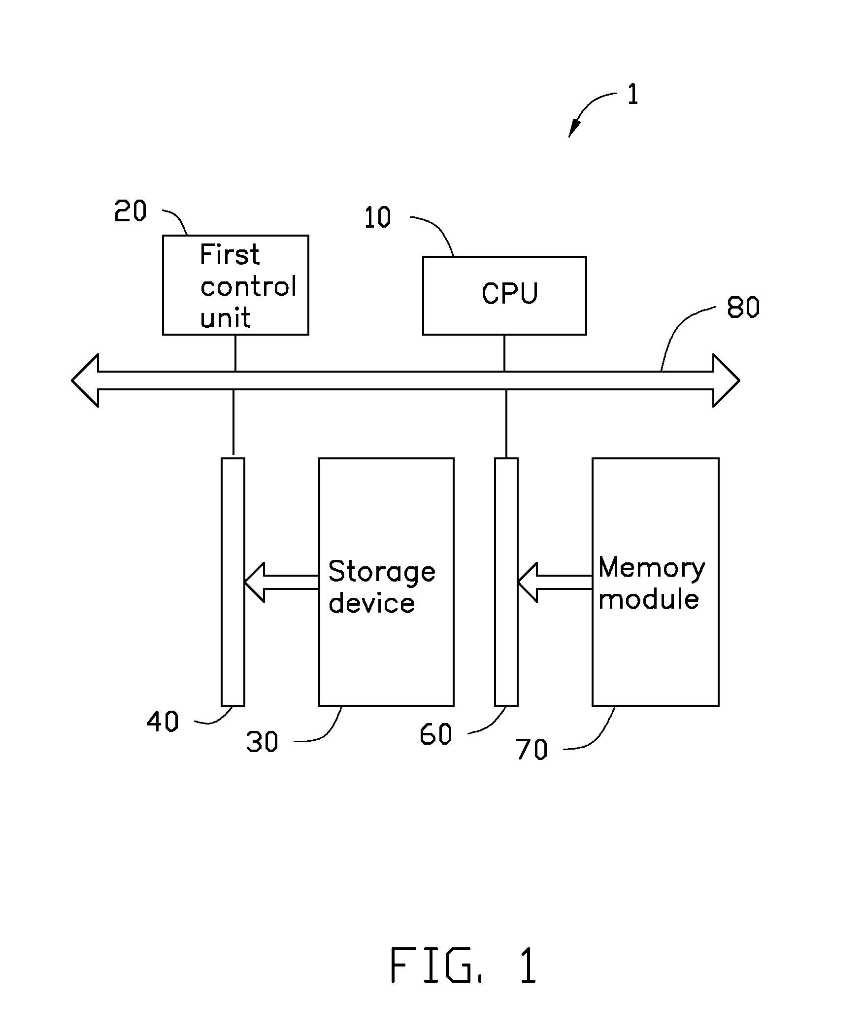
[0010]Referring to FIG. 1, an embodiment of a computing system 1 is shown. The computing system 1 includes a central processing unit (CPU) 10, a first control unit 20, a storage device 30, a first dual inline memory module (DIMM) slot 40, a second DIMM slot 60, a memory module 70, and a first bus 80. The storage device 30 is installed on the first DIMM slot 40, and the memory module 70 is inserted on the second DIMM slot 60. The CPU 10, the first control unit 20, the first DIMM slot 40 and the second DIMM slot 60 are connected to the first bus 80. The first DIMM slot 40 is connected to the second DIMM slot 60 through the first bus 80. In the embodiment, the first control unit 20 is a first direct memory access (DMA) controller, and the CPU controls the reading from and writing to the storage device 30 through the first DMA controller.

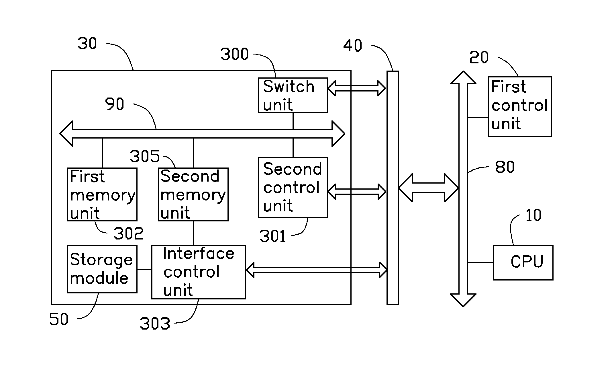
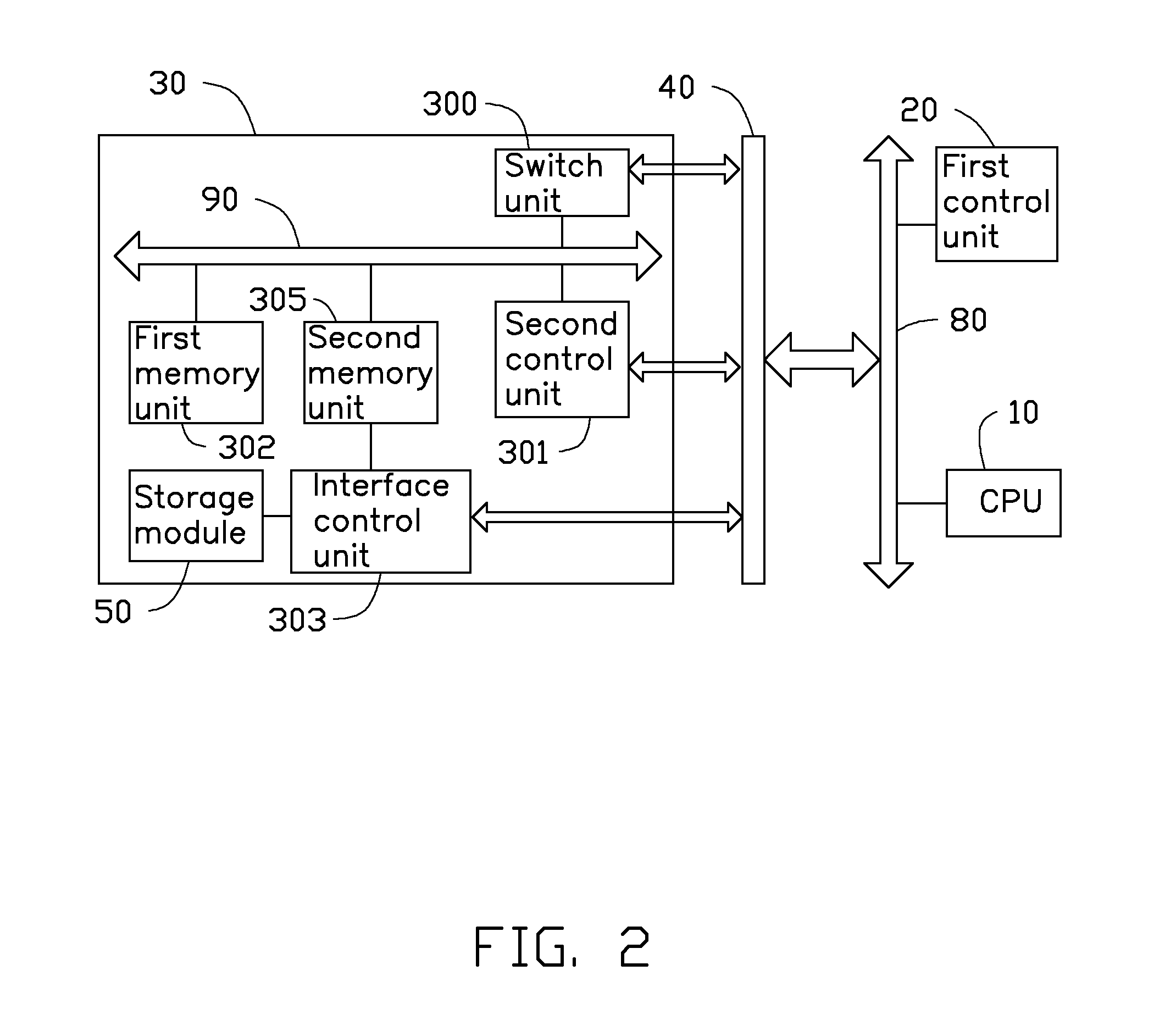
[0011]Referring to FIG. 2, an embodiment of a storage device 30 on the computing system 1 is shown. The storage device 30 includes a storage module 50,...


PUM


Abstract

A computing system includes a central processing unit (CPU), a first direct memory access (DMA) controller, a first bus, a memory module inserted in a first dual inline memory module (DIMM) slot, and a storage device installed on a second DIMM slot. The storage device includes a storage module, a second bus, a memory unit, an interface control unit, and a second DMA controller. The CPU sets up the first and the second DMA controllers to perform data transmission. The first DMA controller controls a first data transmission between the memory module and the memory unit through the first and the second buses, and the second DMA controller controls a second data transmission between the memory unit and the storage module, with the interface control unit, through the second bus. The disclosure further provides a data transmission method of the computing system.

Description

BACKGROUND[0001]1. Technical Field[0002]The present disclosure relates to a computing system, and particularly to a computing system with direct memory access (DMA) controllers and a data transmission method of the computing system.[0003]2. Description of Related Art[0004]There are several dual inline memory module (DIMM) slots for memories in a motherboard of a conventional computing system. However, in many computer systems not all of the DIMM slots are filled with memories. Thus, some of the DIMM slots are free and this means that utilization of the hardware resources of the computing system is less than optimal.[0005]Therefore, there is need for improvement in the art.BRIEF DESCRIPTION OF THE DRAWINGS[0006]Many aspects of the present disclosure can be better understood with reference to the following drawing(s). The components in the drawing(s) are not necessarily drawn to scale, the emphasis instead being placed upon clearly illustrating the principles of the present disclosure...

Claims


Application Information

Patent Timeline
IPC IPC(8): G06F13/16
CPCG06F13/1668
Inventor YANG, FENG-CHI
Owner HON HAI PRECISION IND CO LTD
Why Eureka
Try Eureka