Conveying device

a technology of conveying device and conveying chain, which is applied in the direction of driving chains, manufacturing tools, transportation and packaging, etc., to achieve the effects of simple and rapid assembly, low friction, and simple cleaning

Inactive Publication Date: 2013-10-31
FERAG AG
View PDF8 Cites 23 Cited by
  • Summary
  • Abstract
  • Description
  • Claims
  • Application Information

AI Technical Summary

Benefits of technology

[0009]It is the object of the present invention to then suggest a conveying chain which consists of as little as possible different components, is robust and simple to drive. Moreover, the conveying means should be movable in a reliable manner and with little wear. The connection between the individual chain links should moreover be simple and should be able to be created where possible without any tools. Despite this, the connection should reliably hold in different pivot positions. The conveying chain should moreover be designed in a flexible manner, so that different conveying systems, such as e.g. gripper conveyors or plate conveyors can be realised with the same conveying chain.

Problems solved by technology

This conveying chain has the disadvantage that this is still constructed of a multitude of different components, such as e.g. outer chain links and inner chain links.
Although the conveying system is likewise constructed in a modular manner, individual components or links are only suitable for the design of a certain belt conveyor.

Method used


Image

  • Conveying device
  • Conveying device
  • Conveying device

Examples


Embodiment Construction

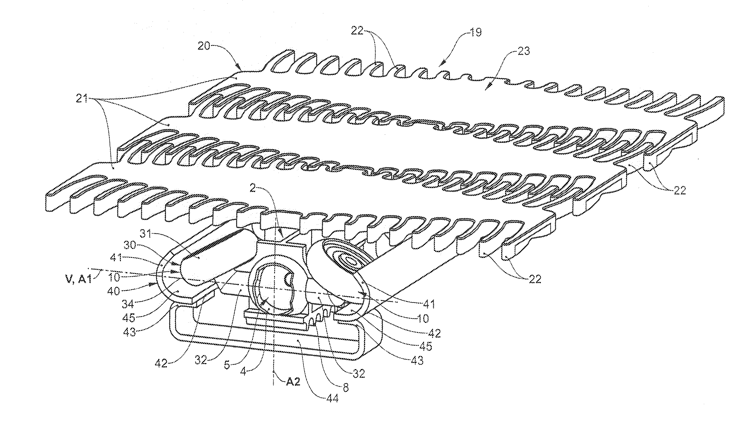
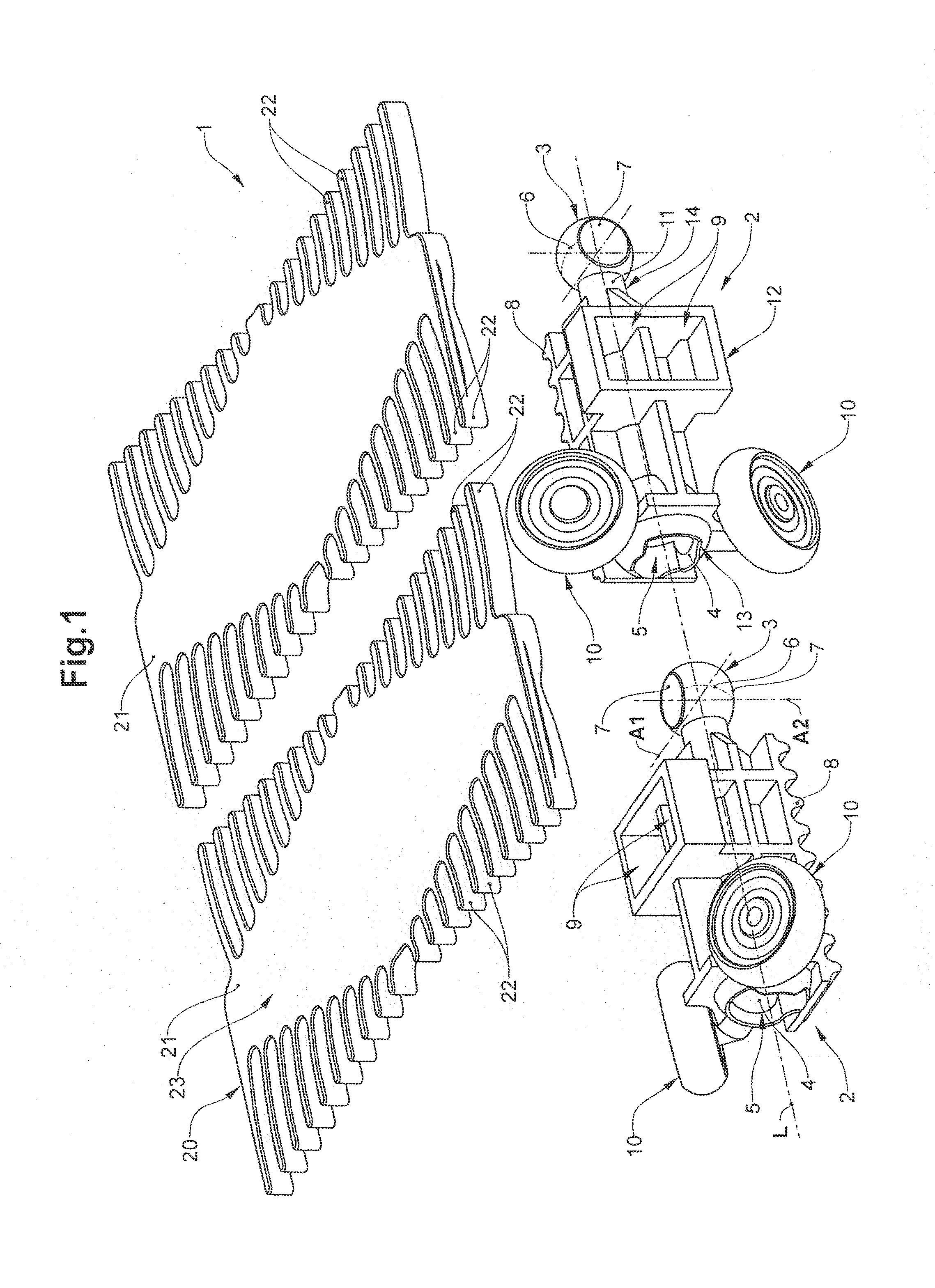
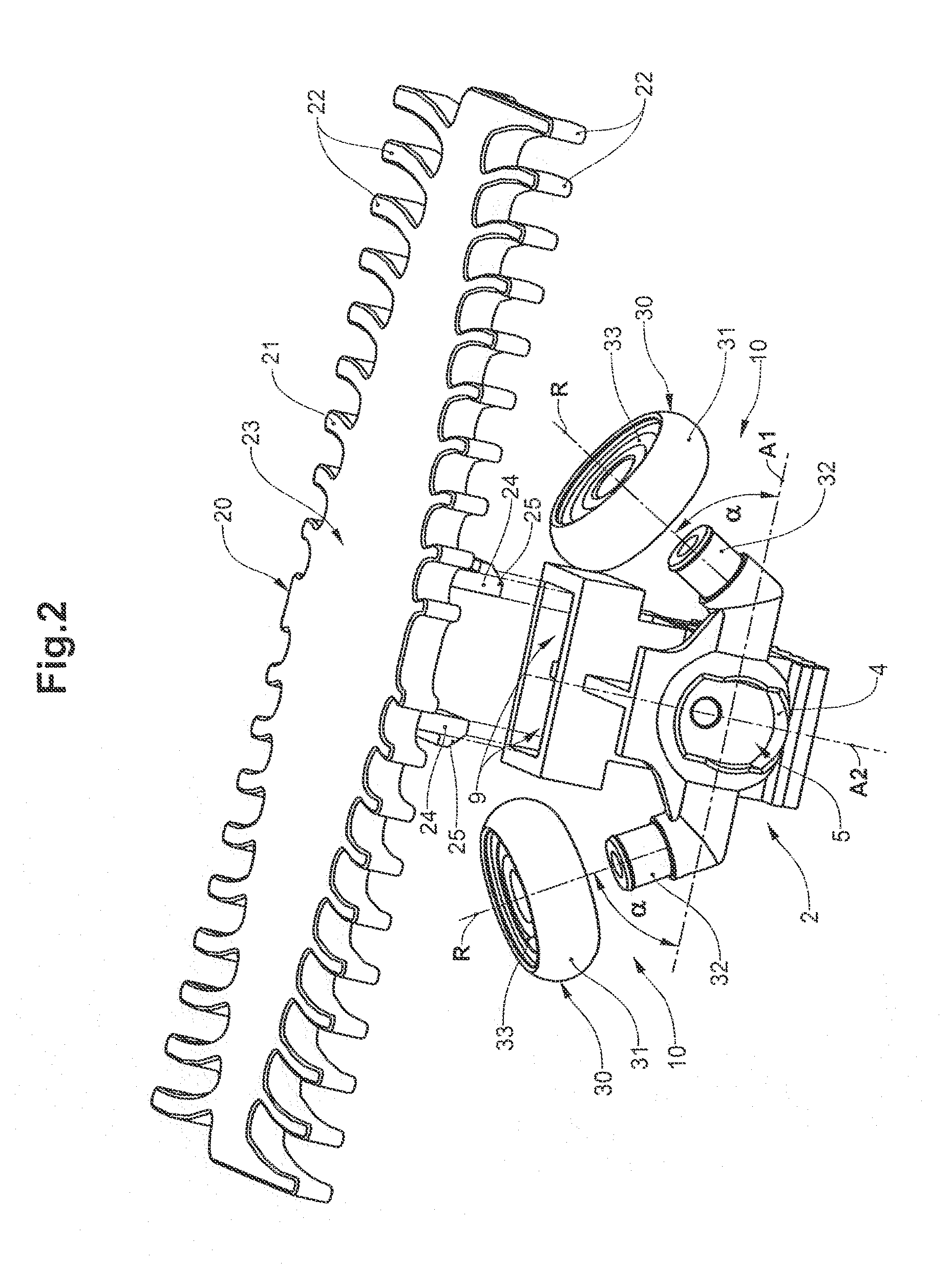
[0089]FIGS. 1, 2 and 3 show a conveying means 1 with chain links 2 which can be led together via an insertion-rotation connection, into a conveying chain. The conveying means further comprises a conveying member 20 with conveying elements 21 in the form of constructionally identical, plate-like carrier elements which are arranged one after the other into a conveying member 20. The plate-like carrier elements 21 form a conveying surface 23, on which the conveyed products are conveyed (not shown). Two connection means in the form of projecting detent hooks 24, via which the carrier elements 21 can be fastened via first connection means 9 onto the chain links 2, are attached on the lower side of the carrier elements 21 which is opposite to the conveying surface 23. The carrier elements 21 at their sides which face the preceding and subsequent conveying element 21 each comprise a plurality of prong-like, slightly bent projections 22 which are distanced to one another. These projections ...


PUM

PropertyMeasurementUnit
angleaaaaaaaaaa
volume percentaaaaaaaaaa
angleaaaaaaaaaa

Abstract

A conveying chain for a conveying means of a conveying device, comprising a plurality of chain links connected to each other. The chain links are connected to each other by means of articulated connections so as to each be pivotable about a first axis and about a second axis oriented perpendicular to the first axis in order to form the conveying chain. The conveying chain is constructed of identical chain links. The chain links each comprise a receptacle on a first end section and a coupling body on a second end section that engages in the receptacle of an adjacent chain link, wherein the receptacle and the coupling body are shaped in such a way that the receptacle and the coupling body can be connected to each other by means of an insertion-rotation motion in order to form the articulated connection.

Description

BACKGROUND OF THE INVENTION[0001]1. Field of the Invention[0002]The invention relates to a conveying chain for a conveying means of a conveying device, comprising a plurality of chain links which are connected to one another, wherein the chain links via joint connections are connected to one another in a manner pivotable in each case about a first axis and a second axis aligned perpendicularly to the first axis, into the conveying chain. The invention moreover relates to a chain link for a conveying chain according to the invention.[0003]2. Description of Related Art[0004]Chain conveyors, with which a conveying member, such as grippers or plate elements for example, is led along a revolving track through a conveying device by way of a conveying chain, are generally known.[0005]Thus for example, the document EP-A-1 975 093 describes a side bow conveying chain which is formed from inner chain links and outer chain links. The individual chain links are connected to one another via a ty...

Claims


Application Information

Patent Timeline
Patent Type & Authority Applications(United States)
IPC IPC(8): B65G15/30
CPCB65G15/30B65G17/066B65G17/086B65G17/385B65G17/44B65G21/22B65G39/20Y10T29/49826B65G17/06B65G17/38F16G13/10
Inventor STUDER, BEAT
Owner FERAG AG
Why Eureka
Try Eureka