X-Ray Tube with Rotating Anode Aperture

a technology of rotating anodes and x-ray tubes, which is applied in the direction of x-ray tubes, x-ray tube targets and convertors, nuclear engineering, etc., can solve the problem of limiting the acceptable current for a given focal spot siz

Active Publication Date: 2013-10-31
AMERICAN SCI & ENG INC
View PDF19 Cites 10 Cited by
  • Summary
  • Abstract
  • Description
  • Claims
  • Application Information

AI Technical Summary

Problems solved by technology

For imaging purposes, a small electron beam focal spot is desirable, however anode heating limits the acceptable current for a given focal spot size.

Method used


Image

  • X-Ray Tube with Rotating Anode Aperture
  • X-Ray Tube with Rotating Anode Aperture
  • X-Ray Tube with Rotating Anode Aperture

Examples


Embodiment Construction

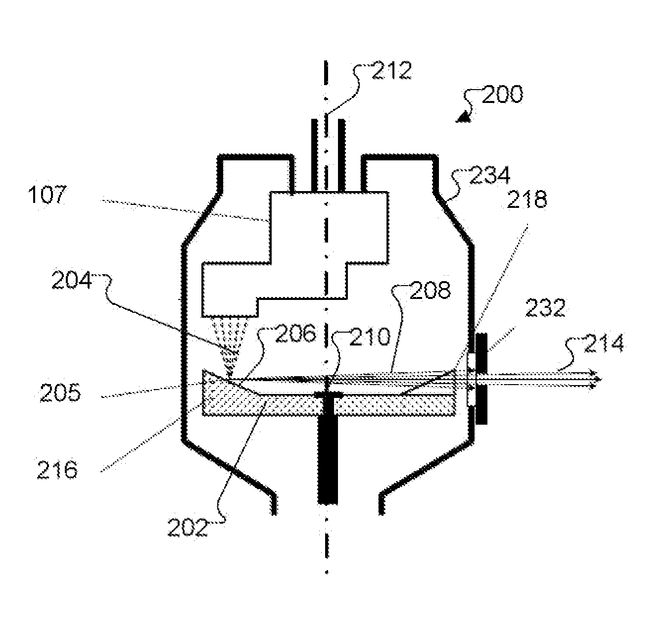
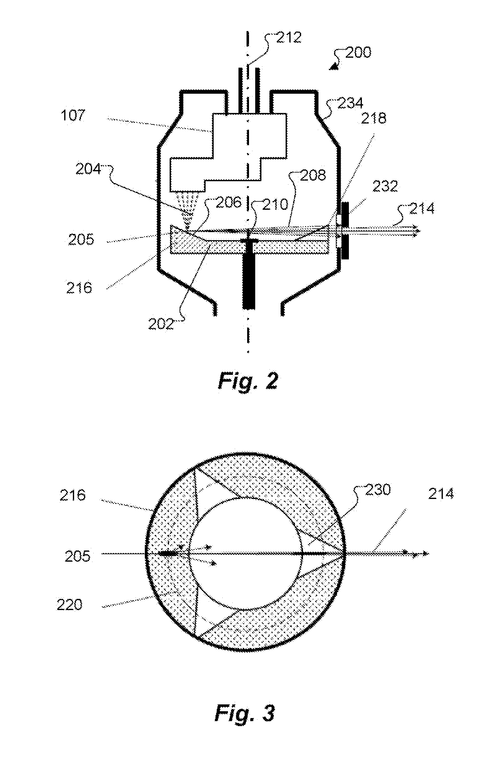
[0006]In accordance with various embodiments of the present invention, an X-ray tube is provided that both generates and collimates an X-ray beam. The X-ray tube has a vacuum enclosure, a cathode disposed within the vacuum enclosure for emitting a beam of electrons, and an anode adapted for rotation with respect to the vacuum enclosure about an axis of rotation. The X-ray tube also has at least one collimator opening adapted for co-rotation with respect to the anode within the vacuum enclosure.

[0007]In accordance with other embodiments of the present invention, the collimator opening or openings may be disposed within the anode itself Each collimator opening may be contiguous with a wedge opening in the anode.

[0008]In accordance with further embodiments of the present invention, the X-ray tube may have an external collimator opening disposed outside the vacuum enclosure. The collimator openings (or opening) may be disposed above a plane transverse to the axis of rotation containing ...


PUM


Abstract

An x-ray tube for generating a sweeping x-ray beam. A cathode is disposed within a vacuum enclosure and emits a beam of electrons attracted toward an anode. The anode is adapted for rotation with respect to the vacuum enclosure about an axis of rotation. At least one collimator opening corotates with the anode within the vacuum enclosure, such that a swept x-ray beam is emitted.

Description

[0001]The present application claims priority from U.S. Provisional Patent Application Ser. No. 61 / 638,555, filed Apr. 26, 2012, and incorporated herein by reference.TECHNICAL FIELD[0002]The present invention relates to sources of X-ray radiation, and, more particularly, to an X-ray tube with a rotating anode.BACKGROUND OF THE INVENTION[0003]X-ray backscatter imaging relies on scanning an object with a well-collimated beam, typically referred to as “pencil beam”. Several approaches for forming the collimated scanning beam have been suggested. Commonly, beam formation and steering relies on an aperture moving in front of a stationary X-ray tube. In most cases the radiation from an X-ray tube is first collimated into a fan beam by a stationary collimator. Then, a moving part with an opening forms a scanning beam. This moving part can be, for example, a rotating disk with radial slits, or a wheel with openings at the perimeter. The rotating disk covers the fan beam and the scanning bea...

Claims


Application Information

Patent Timeline
Patent Type & Authority Applications(United States)
IPC IPC(8): H01J35/10
CPCH01J35/10H01J2235/086G21K1/043H01J35/16H01J2235/06H01J2235/16
Inventor ROMMEL, MARTINROTHSCHILD, PETER
Owner AMERICAN SCI & ENG INC
Why Eureka
Try Eureka