Noise reduction unit for vacuum suction drains

a technology of vacuum suction and noise reduction, which is applied in the direction of sewer systems, sewage draining, construction, etc., can solve the problems of passengers being uncomfortable and the noise level of loud noise, and achieve the effect of improving the noise damping characteristics

Active Publication Date: 2013-10-31
AIRBUS OPERATIONS GMBH
View PDF24 Cites 18 Cited by
  • Summary
  • Abstract
  • Description
  • Claims
  • Application Information

AI Technical Summary

Benefits of technology

[0008]An aspect of the present invention may provide an alternative noise reduc

Problems solved by technology

In the case of toilets with a pneumatic conveyor system in aircraft systems, often a loud noise level arises.

Method used


Image

  • Noise reduction unit for vacuum suction drains
  • Noise reduction unit for vacuum suction drains
  • Noise reduction unit for vacuum suction drains

Examples


Embodiment Construction

[0078]It should be noted that the same reference signs may be used for similar or identical elements.

[0079]The illustrations in the figures are diagrammatic and not to scale.

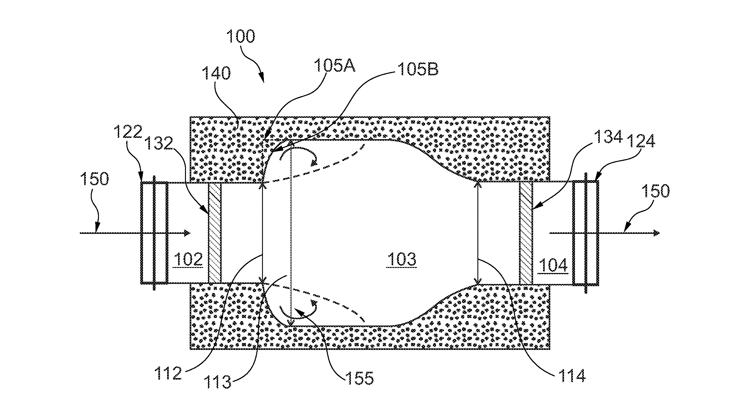
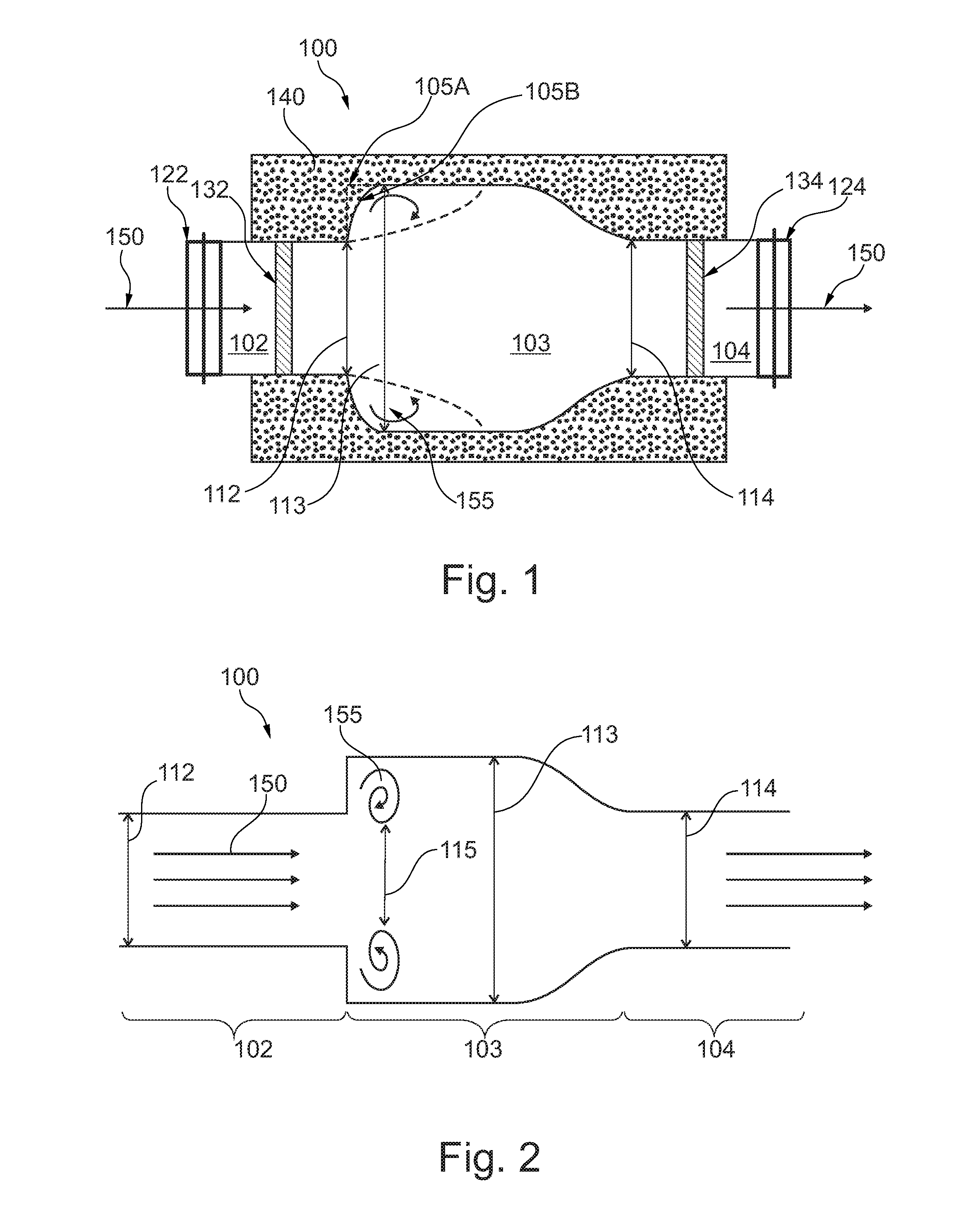
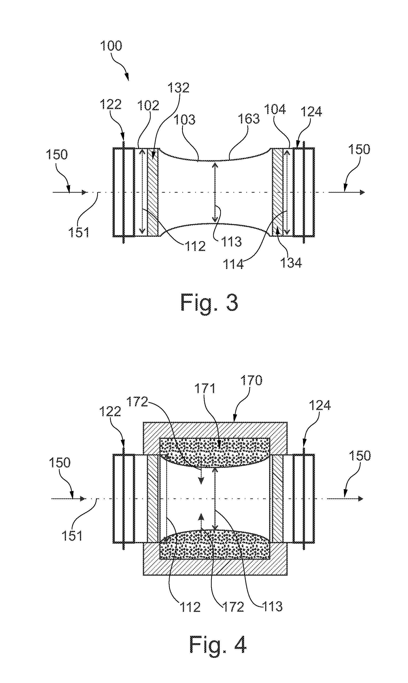
[0080]FIG. 1 illustrates a noise reduction unit 100 with an inlet section 102, a middle section 103 and an outlet section 104. The inlet section comprises a first connector 122 and the outlet section comprises a second connector 124, each for connecting the noise reduction unit into a vacuum suction drain (not shown). A noise insulation element 140 surrounds or encloses the noise reduction unit circumferential. The inlet section comprises a first damper 132 and the outlet section comprises a second damper 134.

[0081]The inlet section 102 has a first diameter 112, the middle section 103 has a second diameter 113 and the outlet section 104 has a third diameter 114.

[0082]The noise reduction unit 100 is adapted to be flown through by material to be conveyed in the direction of the arrow 150, i.e. from the inlet secti...


PUM


Abstract

A noise reduction unit for inserting in a vacuum suction drain is adapted to be flown through by a material to be conveyed through the vacuum suction drain and comprises an inlet section with a first diameter, a middle section with a second diameter and an outlet section with a third diameter. The middle section is adapted to affect a flow velocity reduction of the material to be conveyed such that the noise level arising during the conveying process is being reduced.

Description

CROSS-REFERENCE TO RELATED APPLICATIONS[0001]This application claims the benefit of the filing date of European patent application no. 12 165 713.4 filed Apr. 26, 2012, and of U.S. Provisional Patent Application No. 61 / 638,608 filed Apr. 26, 2012, the disclosures of which are hereby incorporated herein by reference in their entirety.FIELD OF THE INVENTION[0002]The present invention relates to a noise reduction unit for inserting in a vacuum suction drain, a vacuum system and an aircraft with a vacuum system.BACKGROUND OF THE INVENTION[0003]The term “vacuum system” and “vacuum suction drain” refers to special pneumatic conveyors. Generally speaking, in such conveyors transportation takes place in that a pressure difference is applied to the material to be conveyed, i.e. the material to be conveyed is entrained in the fluid flow generated as a result of the pressure difference, wherein generally speaking air is used as the transport medium.[0004]Especially in aircraft, vacuum systems ...

Claims


Application Information

Patent Timeline
IPC IPC(8): B65G53/54
CPCB65G53/54B64D11/02E03F1/006
Inventor SEIBT, CHRISTIANMUELLER, MATTHIAS
Owner AIRBUS OPERATIONS GMBH
Why Eureka
Try Eureka