System and method for automatically measuring uplink noise level of distributed antenna system

a distributed antenna and noise level technology, applied in the field of automatic analysis, can solve the problems of not being able to check the status of an uplink path, das may not be able to check for conditions, and be unable to take measurements, so as to reduce the gain of the uplink

Active Publication Date: 2013-12-19
ADVANCED RF TECH
View PDF8 Cites 83 Cited by
  • Summary
  • Abstract
  • Description
  • Claims
  • Application Information

AI Technical Summary

Benefits of technology

[0019]The determining the external spurious signal input status or the self-oscillation status may include: lowering an uplink gain of the DAS by an offset; comparing the noise level with a comparison value obtained by reducing the upper limit threshold value by the offset; and determining the external spurious signal input status if the noise level is higher than the comparison value and determining the self-oscillation status if the noise level is not higher than the comparison value.

Problems solved by technology

However, after being installed and while operating, a conventional DAS may not be able to check the status of an uplink path.
For example, the DAS may not be able to check for conditions such as a deteriorated gain status of an uplink path, self-oscillations attributable to the influence of an antenna of a specific RU uplink, or an inflow of external spurious signals.
In such cases, it may only be possible to take measurements at the point when a terminal user senses a deterioration of quality and makes a complaint.
Furthermore, a conventional DAS may be problematic in that, in the case where a plurality of RUs is installed, two or more persons may be needed to check the status of an uplink path.
Accordingly, there may be problems in that measurements relating to the status of an RU cannot be taken promptly and the status of an RU cannot be checked in an area where the RU is inaccessible to people.

Method used


Image

  • System and method for automatically measuring uplink noise level of distributed antenna system
  • System and method for automatically measuring uplink noise level of distributed antenna system
  • System and method for automatically measuring uplink noise level of distributed antenna system

Examples


Embodiment Construction

[0033]Example embodiments of the present invention will be described in detail below, with reference to the accompanying drawings, to such an extent that those skilled in the art should be able to implement the technical spirit of embodiments according to the present invention. Reference now should be made to the drawings, throughout which the same reference numerals are used to designate the same or similar components. In the following description, redundant descriptions and detailed descriptions of known elements or functions that may be unnecessary to understand the thrust of the present invention may be omitted.

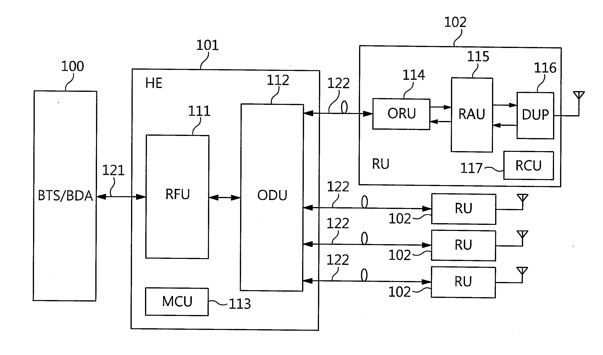
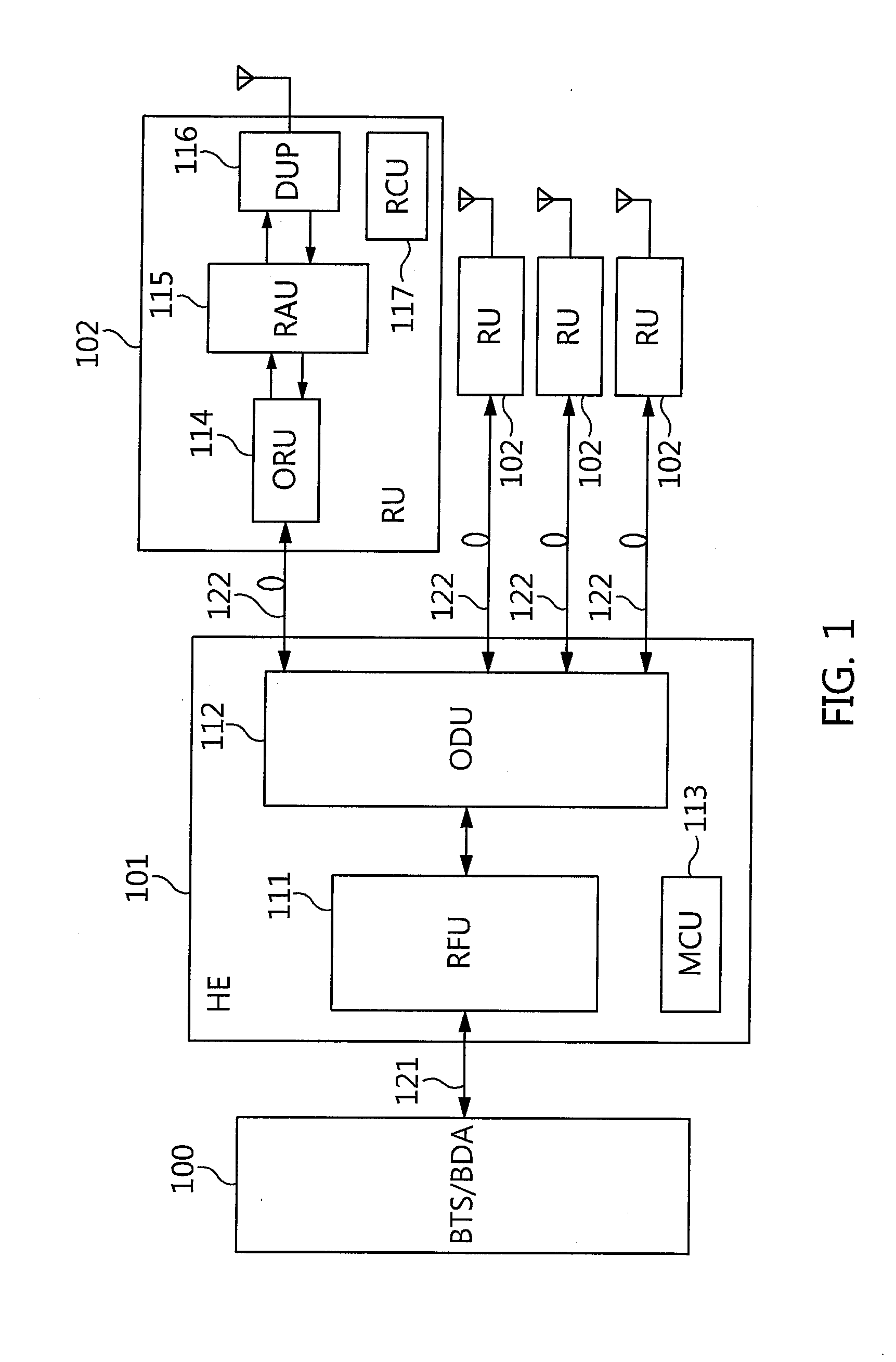
[0034]FIG. 1 is a diagram illustrating a configuration of a DAS. As shown in FIG. 1, a DAS may include an HE 101 and a plurality of RUs 102. The HE 101 may be coupled to a BTS / BDA 100 via an RF interface 121, and may be optically extended to the RUs 102. The RUs 102 may be coupled to the HE 101 over optical cables 122. Each of the RUs 102 may send a signal to a terminal (...


PUM


Abstract

A method of automatically measuring noise levels of a plurality of uplink paths in a Distributed Antenna System (DAS) includes: sequentially measuring a noise level of each uplink path of the plurality of uplink paths; extracting the noise level of each uplink path at a final end of the uplink path; detecting the noise level of each uplink path; and determining a status of each uplink path by comparing the detected noise level with a threshold value.

Description

CROSS-REFERENCE TO RELATED APPLICATION[0001]This non-provisional application claims priority to and the benefit of U.S. Provisional Application No. 61 / 659,761, filed Jun. 14, 2012, the entire content of which is incorporated herein by reference.BACKGROUND[0002]1. Technical Field[0003]The present invention relates generally to a method of automatically analyzing (e.g., measuring) an uplink path of a Distributed Antenna System (DAS). More particularly, the invention relates to a system and method for automatically measuring an uplink noise level of a DAS, measuring the noise level of each Remote Unit (RU) link of a plurality of RU links, at the final end of an uplink path, and then using the noise level to check the status of the uplink path of the DAS.[0004]2. Description of Related Art[0005]In general, a DAS includes a Base Station Transceiver Subsystem (BTS), a Head End (HE), and a plurality of Remote Units (RUs). The DAS may be located in (or placed in) shadow areas that radio wav...

Claims


Application Information

Patent Timeline
Patent Type & Authority Applications(United States)
IPC IPC(8): H04W24/00
CPCH04W24/00H04W24/04H04W88/085H04B7/024H04B17/23H04B17/345
Inventor KO, YOUNG-HOON
Owner ADVANCED RF TECH
Why Eureka
Try Eureka