Elevator safety circuit monitor and control for drive and brake

a safety circuit and control technology, applied in the direction of elevators, alarms, instruments, etc., can solve the problems of contactors and relays that require appreciable financial expenditure, wear of mechanical contacts in use, and appreciable noise emissions, so as to reduce manufacturing costs, avoid electrically conductive separation locations, and reduce noise

Inactive Publication Date: 2000-05-02
INVENTIO AG
View PDF11 Cites 91 Cited by
  • Summary
  • Abstract
  • Description
  • Claims
  • Application Information

AI Technical Summary

Benefits of technology

Advantages achieved by the invention are that the monitoring equipment consists of a safety circuit sensor system and a motor-switching and brake-switching circuit, which stand in connection one with the other, wherein the monitoring equipment consists exclusively of electronic components while avoiding electrically conductive separating locations. Due to the use of electronic components, electromechanical switching elements, which have electrically conductive separating locations, can be dispensed with. Through the use exclusively of electronic components, an appreciable reduction in the noise level is achieved, since no switching noises any longer arise. This has an advantageous effect particularly in the case of elevator installations without machine room. Furthermore, due to the use of usual electronic components, the manufacturing costs can be significantly reduced and a high security and reliability of the monitoring equipment can, in addition, be ensured.

Problems solved by technology

With electromechanical relays or also contactors, the mechanical contacts wear in use.
Furthermore, contactors or relays cause appreciable noise emissions, which prove to be disturbing particularly in the case of elevator installations in residential or commercial buildings, during switching operations.
Finally, contactors and relays require appreciable financial expenditure also by reason of their limited service life and frequent exchange.
Disadvantages also result due to the manner of operation of the safety circuit.
However, this entails the following diverse disadvantages in an alternating current safety circuit:
The service life of the contactors and relays is greatly restricted by reason of the mechanical wear.
Equally, disadvantages result in the case of a direct current safety circuit:
The direct current leads to wear at the contact transitions of the safety contacts due to material migration.
In the case of the monitoring equipment described above, switching devices are used, which indeed eliminate the disadvantages of electromechanical switches, but are more expensive by a multiple, so that use is not worthwhile on cost grounds.
Furthermore, this monitoring equipment requires complex electrical circuitry.

Method used


Image

  • Elevator safety circuit monitor and control for drive and brake
  • Elevator safety circuit monitor and control for drive and brake
  • Elevator safety circuit monitor and control for drive and brake

Examples


first embodiment

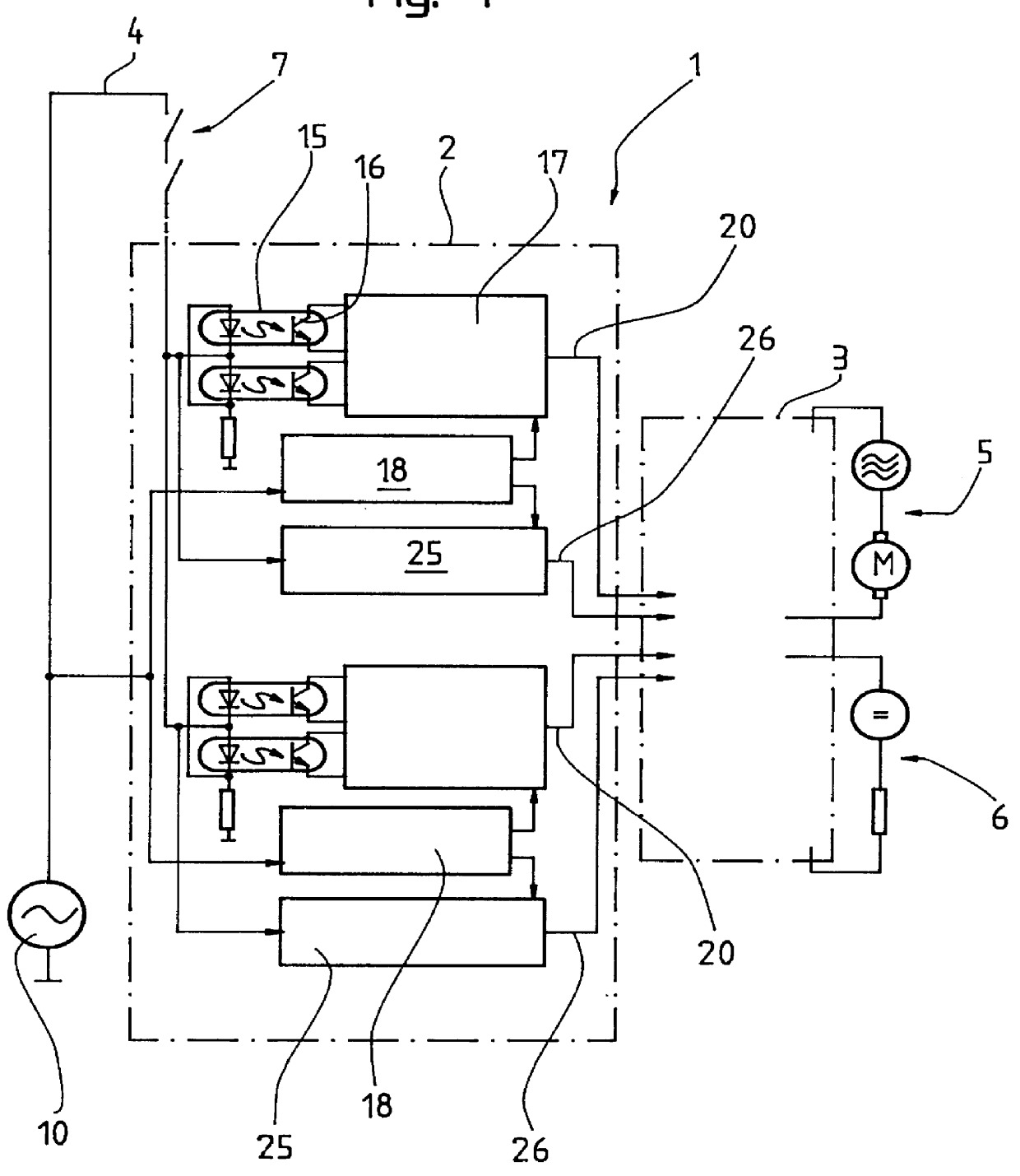
A schematic illustration of monitoring equipment 1 for an elevator drive control according to the present invention with a safety circuit sensor system 2 and a motor-switching and brake-switching circuit 3 for an alternating current safety circuit 4 is shown in the FIG. 1. The safety circuit sensor system 2 is responsible for the monitoring of the safety circuit 4, for example whether the safety circuit is open or closed. The motor-switching and brake-switching circuit 3 is responsible for the consequential actions resulting therefrom with respect to an elevator drive motor 5 and an associated brake 6, respectively. Several contacts 7, which must be monitored, are present, for example at the elevator shaft doors, in the safety circuit 4, which is looped through the elevator car and shaft.

A solution for the alternating current safety circuit 4 and the safety circuit sensor system 2 is described in the following, with values by way of example.

A signal source 10 of the safety circuit 4...

second embodiment

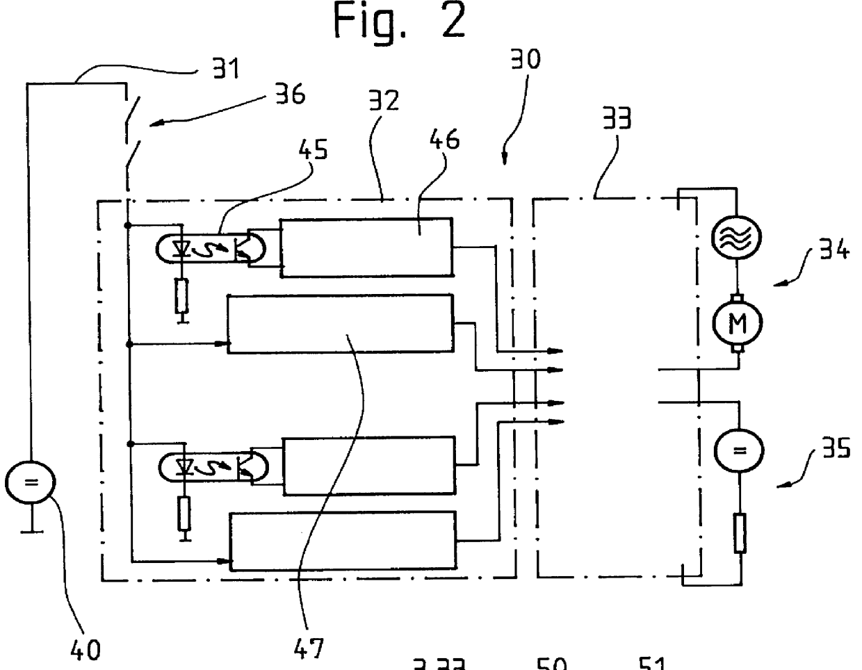
A schematic illustration of a second embodiment monitoring equipment 30 according to the present invention for a direct current safety circuit 31 with a safety circuit sensor system 32 and a motor-switching and brake-switching circuit 33 is shown in the FIG. 2. The safety circuit sensor system 32 is responsible for the monitoring of the safety circuit 31 and the motor-switching and brake-switching circuit 33 for the consequential actions resulting therefrom with respect to an elevator drive motor 34 and an associated brake 35, respectively. Several contacts 36, which must be monitored and are, for example, at the shaft doors, are present in the safety circuit 31, which is looped through the elevator car and the shaft.

The safety circuit sensor system 32 with the safety circuit 31 operated by direct current is much simpler than the alternating current version discussed above, as is already evident from FIG. 2.

The synchronization with the source signal becomes superfluous and the evalu...


PUM


Abstract

Monitoring equipment for an elevator drive control includes two modules, a safety circuit sensor system and a motor-switching and/or brake-switching circuit, wherein the monitoring of a safety circuit and the consequential actions resulting therefrom takes place exclusively by means of electronic components while avoiding electrically conductive separating locations. By the use of electronic components, electromechanical switching elements, which have electrically conductive separating locations, can be dispensed with. In addition, an appreciable reduction in the noise level is achieved, since switching noises no longer arise. This has an advantageous effect particularly in the case of elevator installations without a machine room. Furthermore, the manufacturing costs can be significantly reduced and a high security and reliability of the monitoring equipment can be ensured by the use of usual electronic components.

Description

BACKGROUND OF THE INVENTIONThe invention concerns equipment for monitoring an elevator drive control and, in particular, equipment for monitoring a safety circuit of an elevator drive control.In the case of present day elevator installations with frequency converter drives and microprocessor controls, mainly electromechanical contactors are used for the monitoring of the safety circuit and the consequential actions connected therewith, such as the brake actuation, the switching-on and switching-off of motor current and the loading of the intermediate circuit of the frequency converter with a defined switching-on current.With electromechanical relays or also contactors, the mechanical contacts wear in use. Furthermore, contactors or relays cause appreciable noise emissions, which prove to be disturbing particularly in the case of elevator installations in residential or commercial buildings, during switching operations. Finally, contactors and relays require appreciable financial exp...

Claims


Application Information

Patent Timeline
Patent Type & Authority Patents(United States)
IPC IPC(8): B66B5/00G05B9/02
CPCB66B5/0031
Inventor GERSTENKORN, BERNHARD
Owner INVENTIO AG
Why Eureka
Try Eureka