Rotation pointed antenna for fixed wireless wide area networks
a fixed wireless wide area network and antenna technology, applied in the field of wireless communication systems, can solve the problems of limited wireless voice and data services, inability to transmit power or receive enough signal strength to communicate in certain areas, and affect the coverage and capacity of wireless networks
- Summary
- Abstract
- Description
- Claims
- Application Information
AI Technical Summary
Benefits of technology
Problems solved by technology
Method used
Image
Examples
first embodiment
[0059]FIG. 5(a) is a cross-section side view of the cantenna 16, according to a As shown, the cantenna 16 is a closed cylinder comprised of the housing 64 mounted on the base.
[0060]66, the antenna assembly is rotatably mounted within the closed cylinder, and the motor 68 mechanically rotates the antenna assembly about a central axis of the closed cylinder.
[0061]The housing 64 is typically transparent to the frequencies of interest being transmitted and received by the antenna 40. In one embodiment, these frequencies are in ranges of the 700, 1900, or 1700 / 2100 MHz, but can be of any frequency range without departing from the scope of the present specification.
[0062]The base 66 is a structural element that supports the other elements of the cantenna 16. Preferably, the base 66 engages with the housing 64 in a manner that encloses all of other components of the cantenna 16 in a weather-proof package
[0063]As shown in FIG. 5(a), the antenna assembly may be comprised of two PCBs 72 and ...
second embodiment
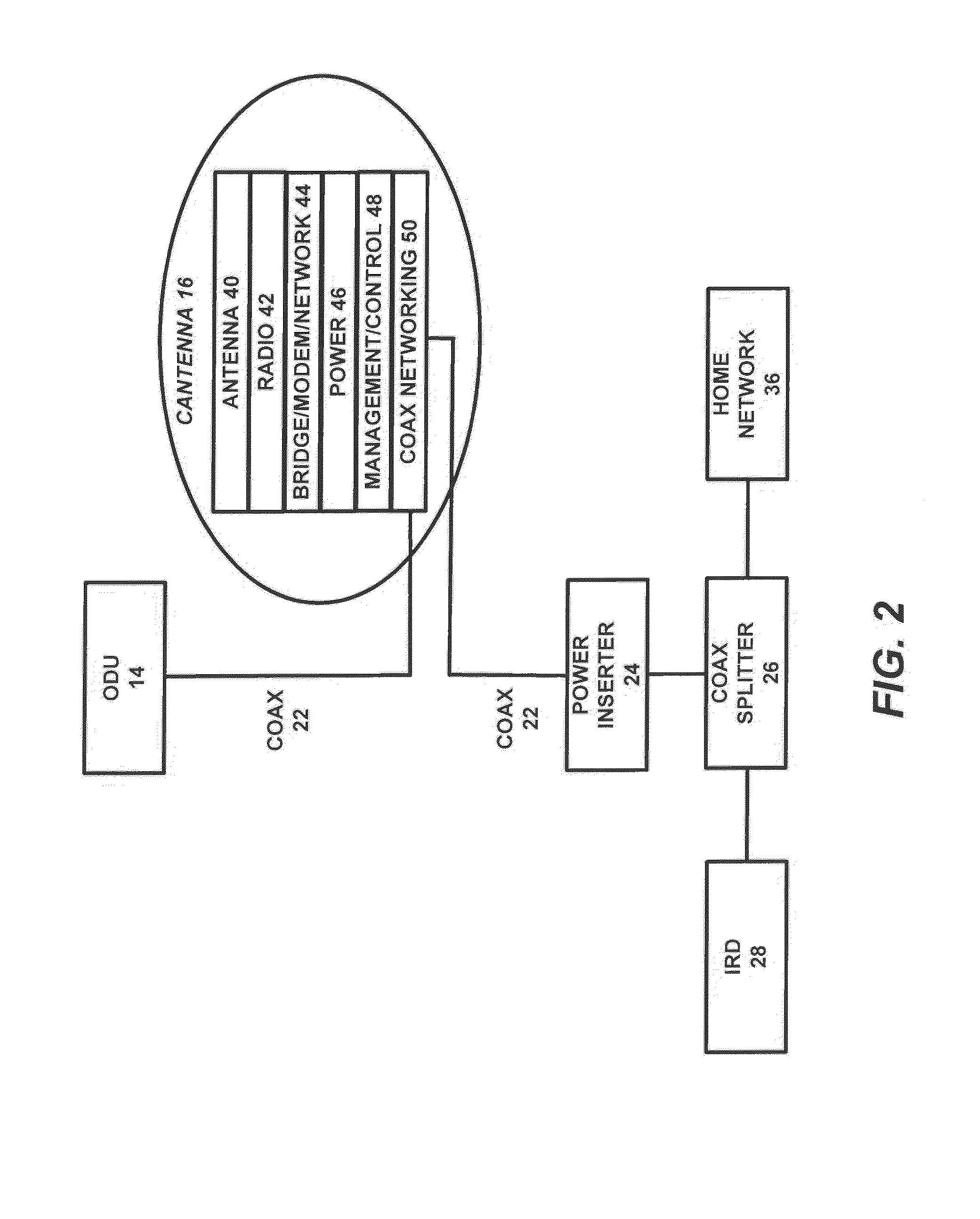
[0074]FIG. 5(b) is a cross-section side view of the cantenna 16, according to a In this embodiment, the modules 42, 44, 46, 48 and 50 are implemented on a single PCB 74 that is mounted on and fixed to the base 66 of the housing 64, wherein only the PCB 72 implementing the antenna 40 is rotated. Similarly, the motor 68 is also mounted on and fixed to the base 66.
[0075]FIG. 5(c) is a cross-section front view of the cantenna 16, according to the second embodiment. A similar view would exist for the first embodiment, except that the PCB 74 implementing the modules 42, 44, 46, 48, 50 would be hidden, because it would be mounted on the opposite side from the PCB 72 implementing the antenna 40, rather than on the base 66.
[0076]FIG. 5(d) is a cross-section top view of the cantenna 16, according to the first Embodiment. The semicircular arrows within the housing 64, on opposite sides of the rotating antenna assembly comprised of the plate 70a, PCB 72, and PCB 74, are intended to indicate on...
PUM
 Abstract
Description
Claims
Application Information
 - R&D
- Intellectual Property
- Life Sciences
- Materials
- Tech Scout
- Unparalleled Data Quality
- Higher Quality Content
- 60% Fewer Hallucinations
Browse by: Latest US Patents, China's latest patents, Technical Efficacy Thesaurus, Application Domain, Technology Topic, Popular Technical Reports.
© 2025 PatSnap. All rights reserved.Legal|Privacy policy|Modern Slavery Act Transparency Statement|Sitemap|About US| Contact US: help@patsnap.com


