Device for assisting joint exercise

a technology for assisting joints and joints, applied in the field of assisting joints, can solve the problems of difficult use of exoskeleton type assistance devices, inconvenient maintenance, and large effort and time, and achieve the effects of convenient adjustment, excellent maintenance, and convenient adjustment of the length of the assist force transmission band 82

Inactive Publication Date: 2013-10-31
SUMITOMO RIKO CO LTD +1
View PDF15 Cites 30 Cited by
  • Summary
  • Abstract
  • Description
  • Claims
  • Application Information

AI Technical Summary

Benefits of technology

[0099]Furthermore, with the third traction band 88, one of the end parts extends circling around to the back part from the side part of the lower back, and is fixed to the rotation shaft 42 of the drive device 38 shown in FIG. 4. Meanwhile, the other end part of the third traction band 88 is attached to the drive device support belt 28 of the second mounting section 16 at the front of the lower back. In more detail, a hook fitting 98 is attached to the other end part of the third traction band 88, and that is attached in a state that is detachable to a ring shaped or half ring shaped attachment fitting 100 provided on the front surface part of the drive device support belt 28. A plurality of the attachment fittings 100 are provided aligned in the circumference direction on the drive device support belt 28, and by suitably selecting from among that plurality the attachment fitting 100 for attaching the hook fitting 98, it is possible to adjust the length of the third traction band 88.
[0100]By the description above, with the device for assisting joint exercise 80, the first mounting section 14 and the second mounting section 16 are connected by the assist force transmission band 82 constituted by the first through third traction bands 84, 86, and 88. With this arrangement, tensile force is exerted between the first mounting section 14 and the second mounting section 16 through the assist force transmission band 82. Then, the same as with the first embodiment, when doing hip joint bending and extending exercise, assist force is exerted using tensile force, which assists walking.
[0101]Also, with this embodiment, the assist force transmission band 82 is constituted by the first through third traction bands 84, 86, and 88, and they are respectively connected by the connecting fittings 92 and 94. Because of that, in cases such as when any of the first through third traction bands 84, 86, and 88 are damaged, it is possible to remove and replace just the damaged part from the connecting fittings 92 and 94, so maintainability is excellent.
[0102]Also, if replaced with an item for which the lengths of the first to third traction bands 84, 86, and 88 are different according to the physical build of the user (thigh length and the like), it is possible for users with a wide range of physical builds to use this. Therefore, it is possible to also handle cases such as when a large number of unidentified users are using them in a rehabilitation center of a hospital or the like, for example. Furthermore, since a plurality of attachment fittings 100 are provided aligned laterally, by changing the attachment position of the hook fittings 98, it is possible to change the vertical direction length of the assist force transmission band 82. Thus, it is possible to easily perform adjustments according to differences in physical build. In addition, since an adjustable fitting 90 is provided on the second traction band 86, it is possible to easily adjust the length of the assist force transmission band 82 by adjusting the length of the second traction band 86.

Problems solved by technology

However, with assistive devices using this kind of hard exoskeleton, it was necessary to accurately measure the physical build of the user (thigh and lower leg length and the like) and to precisely adjust the length of the exoskeleton arm, and when this adjustment was not done appropriately, excessive force could be applied to the joints during exercise, which could lead to a very dangerous situation.
Also, the work of putting on and taking off the exoskeleton type assistance device is not easy for a user who requires assistance to move, and a great deal of effort and time is required to put it on and take it off.
Because of that, it was difficult to wear and use for everyday purposes with the goal of supplementing reduced muscle strength to make movement easier.
In fact, when using an assistance device having a large exoskeleton, it is virtually impossible for the user to move in resistance to the drive force of the exoskeleton with his own muscle strength, and there was absolutely no consideration taken for using this kind of assistance device for walking training or the like with the goal of efficient strengthening of muscle strength.
Also, to control the movement of the assistance device, it is necessary to perform measurement of the surface electromyography, so there was also the problem of the user having to wear numerous surface electrodes (normally 18).
However, with this kind of structure of US 2011 / 0218466 as well, a hard exoskeleton (arm) that extends along the side surface of the thigh is required, so there were cases when device simplification and lightening were still not sufficient.

Method used


Image

  • Device for assisting joint exercise
  • Device for assisting joint exercise
  • Device for assisting joint exercise

Examples


first embodiment

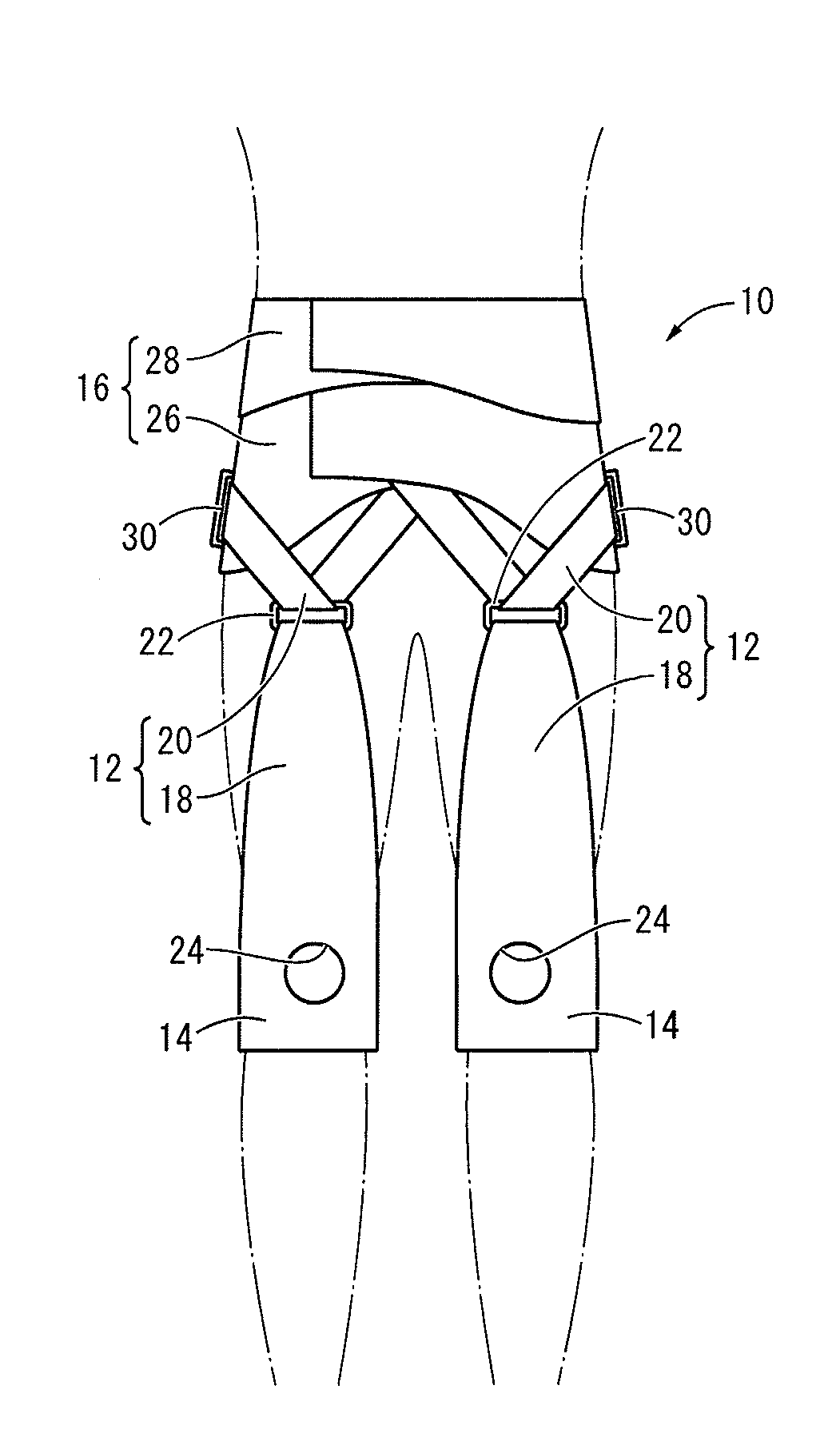
[0052]FIG. 1 and FIG. 2 show a device for assisting joint exercise 10 as the present invention. The device for assisting joint exercise 10 is for assisting bending and extending of the hip joints, and has a constitution including assist force transmission bands 12, 12 as a pair of assist force transmission sections at left and right extending across the hip joints, and a first mounting section 14 and a second mounting section 16 respectively attached to both end parts of the assist force transmission bands 12, 12 so that the first mounting section 14 is attached to one side and the second mounting section 16 is attached to the other side sandwiching the hip joints. In FIG. 1 and FIG. 2, the device for assisting joint exercise 10 is shown in a state worn by the user, and the outline of the user is shown by a double-dot-dash line. Also, in the description hereafter, the front surface means the surface on the user's abdominal side (front surface), the rear surface means the surface on ...

third embodiment

[0088]Also, FIG. 7 and FIG. 8 show a device for assisting joint exercise 60 as the present invention. This device for assisting joint exercise 60 has a main unit 62 exhibiting a pants (leggings) shape which adheres tightly to the body surface covering from the lower back to below the knees. This main unit 62 is formed with fabric that has excellent stretch properties that allow elastic deformation according to the user's body shape, and deforms according to the user's body shape or the like.

[0089]Also, an assist force transmission section 64 is provided on the main unit 62. The assist force transmission section 64 is a thin band shaped fabric, and is equipped integrally with a first traction section 66 extending vertically so as to cover the front surface of the thigh, and a second traction section 68 extending diagonally upward branching left and right at a designated angle from the top end of the first traction section 66. Also, both the first traction section 66 and the second tr...

fourth embodiment

[0095]FIG. 9 shows a device for assisting joint exercise 80 as the present invention. The device for assisting joint exercise 80 has a constitution by which an assist force transmission band 82 as the assist force transmission section connects the first mounting section 14 and the second mounting section 16.

[0096]The assist force transmission band 82 is constituted including a first traction band 84, a second traction band 86, and a third traction band 88. The first through third traction bands 84, 86, and 88 are respectively formed with thin band shaped fabric extending at a generally fixed width dimension. The first and second traction bands 84 and 86 are made to be elastically deformable in the lengthwise direction (in FIG. 9, the vertical direction) which is the action direction of the tensile force by the electric motor 40 of the drive device 38, while the third traction band 88 has elastic deformation restricted in the lengthwise direction. Also, an adjustable fitting 90 is pr...


PUM


Abstract

Provided is a device having a novel configuration and adapted to assist joint exercise. A device for assisting joint exercise that assists bending and extending of a joint including: a flexible assist force transmission section; a first mounting section and a second mounting section, which are provided at both end portions of the assist force transmission section, the first mounting section adapted to be mounted on one site and the second mounting section adapted to be mounted on another site sandwiching a user's joint; a drive source provided that exerts tensile force between the first mounting section and the second mounting section through the assist force transmission section, wherein at least a portion of the assist force transmission section is elastically deformable in an acting direction of the tensile force by the drive source.

Description

INCORPORATED BY REFERENCE[0001]The disclosure of Japanese Patent Application No. 2011-057470 filed on Mar. 16, 2011 including the specification, drawings and abstract is incorporated herein by reference in its entirety. This is a Continuation of International Application No. PCT / JP2012 / 001792 filed on Mar. 14, 2012.BACKGROUND OF THE INVENTION[0002]1. Field of the Invention[0003]The present invention relates to a device for assisting joint exercise which, when a user is bending and extending his joints, exerts on the user an assist force which makes it possible to realize bending and extending, or exerts a load (resist force) for efficiently strengthening the muscle strength required for bending and extending.[0004]2. Description of the Related Art[0005]From the past, to support movement such as walking or the like for physically disabled persons who have lost muscle strength or for elderly persons whose muscle strength has diminished, wearable type movement assistance devices like t...

Claims


Application Information

Patent Timeline
Patent Type & Authority Applications(United States)
IPC IPC(8): A63B21/02
CPCA63B21/02A61H1/0244A61H2201/1215A61H2201/5071A61H2230/605A61H2201/149A63B21/0058A63B23/0482A63B23/0494A63B21/00181A61H1/024A61H3/00A61H2201/14A63B2230/605A63B69/0028A63B71/0009A63B21/068A63B21/151A63B23/03541A63B2022/0094A63B2220/51A63B21/4011A63B21/4009A63B21/4047
Inventor YAMAMOTO, MOTOJITAKASUGI, SHIN-ICHIROSATO, MASANORIHASHIMOTO, KAZUNOBU
Owner SUMITOMO RIKO CO LTD
Why Eureka
Try Eureka