Ultrasound diagnosis apparatus

a technology of ultrasonic and diagnostic equipment, applied in the field of ultrasonic diagnostic equipment, can solve the problems of limited imaged objects, insufficient displacement, difficult pressing, etc., and achieve the effect of high-precision evaluation

Active Publication Date: 2013-10-31
HITACHI MEDICAL CORP
View PDF15 Cites 25 Cited by
  • Summary
  • Abstract
  • Description
  • Claims
  • Application Information

AI Technical Summary

Benefits of technology

[0013]According to the present invention, it can be diagnosed whether there is a part heterogeneous in sonic velocity in a measuring object or not by imaging heterogeneity related to sonic velocity that proceeds from tissue structure based upon the waveform of the shear wave generated by the ultrasonic focused beam.
[0014]Besides, the imaging and the diagnosis of the heterogeneity of sonic velocity caused by frequency dispersion and an amplitude in addition to heterogeneity related to sonic velocity that proceeds from tissue structure are enabled. Further, the higher-precision evaluation of heterogeneity is enabled by the application of a burst chirp mode.
[0015]Furthermore, the application to a diagnostic method of identifying a normal tissue and a malignant tissue based upon a degree of heterogeneity of the present invention is expected.

Problems solved by technology

This method has a problem that an imaged object is limited to internal organs that exist in locations in which pressure from a surface of the body is easy.
For example, as a slide plane as an intervening layer exists between the surface of the body and the liver, it is difficult to press so that sufficient displacement is generated.

Method used


Image

  • Ultrasound diagnosis apparatus
  • Ultrasound diagnosis apparatus
  • Ultrasound diagnosis apparatus

Examples


first embodiment

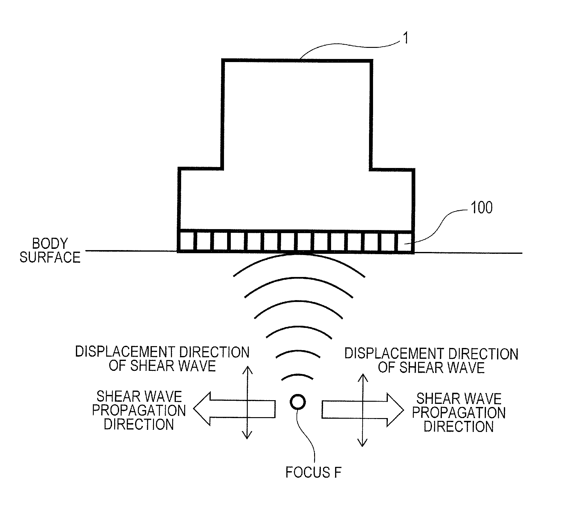
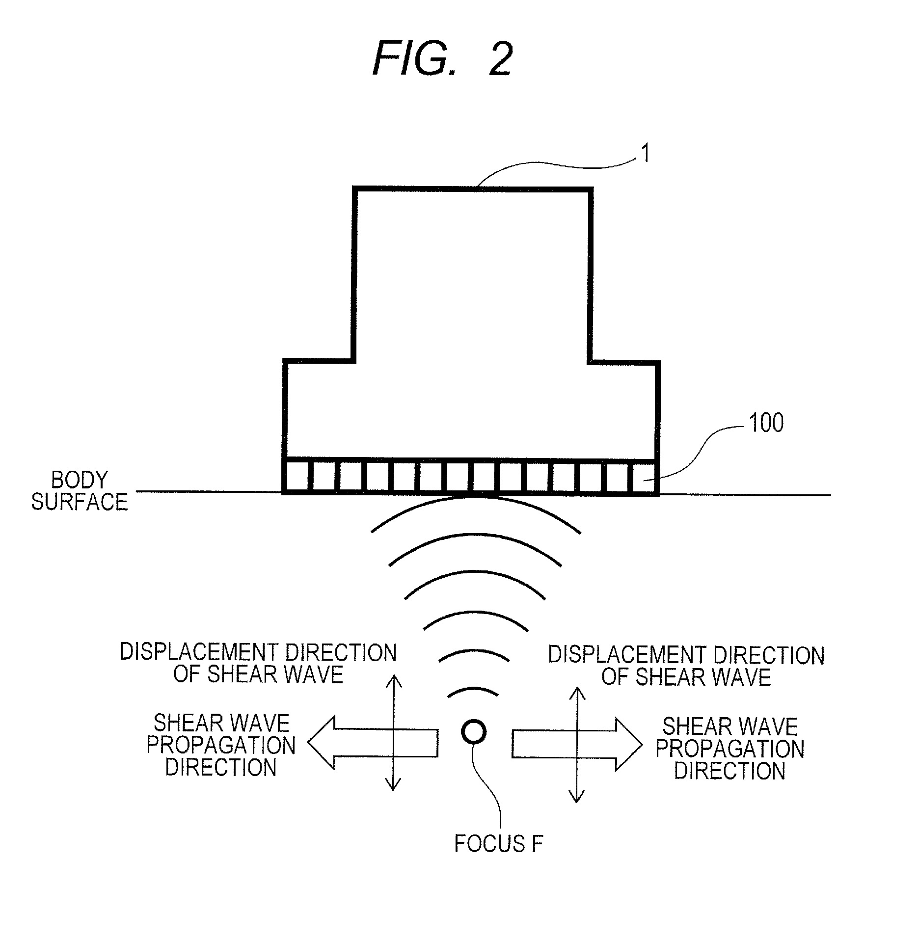
[0044]In this embodiment, as shown in FIG. 2, a case that a linear array type ultrasound probe 1 is touched to a surface of a body of a subject and an ultrasonic beam for generating displacement is focused on a target section in the body will be described. In this case, a case that a direction of the propagation of the ultrasonic beam for generating displacement (=the transmission beam for generating displacement) on the desired section is a direction perpendicular to the body surface will be described.

[0045]As shown in upper and lower halves of FIG. 3, the generation of an ultrasonic beam is realized by calculating distance between each focus and a position of each element 100 of the ultrasound probe 1, allocating delay time calculated by dividing difference in distance among elements by the sonic velocity of an object every element and transmitting the ultrasonic beam. When an ultrasonic beam for generating displacement is radiated onto a focus, radiation pressure is generated acc...

second embodiment

[0070]A second embodiment for evaluating heterogeneity based upon plural temporal waveforms of the displacement of a shear wave in a heterogeneity detecting device 26 will be described referring to FIGS. 10A and 10B below.

[0071]As shown in FIG. 10A, in one method, after a temporal waveform 101 of the displacement of a shear wave is fitted using an arbitrary well-known function, for example, a polynomial function, an exponential function, Gaussian function and others, noise is removed using a low-pass filter and others. Afterward, half-width W having a smaller value than a peak value dp of a fitted waveform 102 by −6 dB as a threshold is calculated. Noise removing processing may be also performed before fitting and noise removing processing may be also omitted. After fitting or after noise is removed, the width of the temporal waveform described in the first embodiment may be also calculated. A value related to heterogeneity may be also calculated based upon a function having time tp...

third embodiment

[0077]In a third embodiment, a method of evaluating the heterogeneity of sonic velocity that proceeds from frequency dispersion will be described using FIGS. 11 and 12.

[0078]For a cause of the heterogeneity of sonic velocity, tissue structure, frequency dispersion, an amplitude and particle velocity can be given. In the first embodiment, the method of evaluating the heterogeneity of sonic velocity that proceeds from tissue structure is described. When there is the heterogeneity of sonic velocity that proceeds from frequency dispersion and when a repetition frequency PRFp in the radiation of a transmission beam for generating displacement has bandwidth, the velocity of a shear wave varies. In this embodiment, the heterogeneity of sonic velocity that proceeds from frequency dispersion will be mainly described.

[0079]FIG. 11 shows a processing flow of the third embodiment in which the heterogeneity of sonic velocity that proceeds from frequency dispersion is measured and evaluated when ...


PUM


Abstract

When multiple tissues having differing speeds of sound are intermixed in the viewing field of a measured subject such as a living body, the invention measures hardness, such as modulus of elasticity or viscosity, with high precision. As a means for detecting heterogeneity of sound speed in the tissues of a subject, a displacement-generating transmission beam is applied from a displacement generating beam-generating device (13) of a displacement-generating unit (10) on an ultrasound probe (1) to irradiate a focused ultrasonic wave into the living tissue and generate a shear wave. From the displacement-time waveforms of multiple positions of the shear wave detected using the displacement detection transmission beam-generating device (22) and the displacement detection received beam-computing device (23) of a displacement-detecting unit (20), at least two pieces of information, such as the integrated value and the maximum amplitude value, are obtained. On the basis of the two pieces of information, a heterogeneity-detecting device (26) of the displacement-detecting unit (20) detects the physical magnitude associated with the heterogeneity in sound speed arising from the tissue structure and displays same on a display (5).

Description

TECHNICAL FIELD[0001]The present invention relates to an ultrasound diagnosis apparatus that detects heterogeneity related to sonic velocity inside a subject by the transmission and reception of ultrasound.BACKGROUND ART[0002]For a method of diagnosing a mammary tumor, cirrhosis, a lesion of a blood vessel and others, a method (elastography) of diagnosing hardness inside a subject based upon an ultrasonic echo signal in place of palpation by a doctor can be given. In the diagnosis of hardness by elastography, an operator presses a probe on a surface of the subject and generates displacement in a tissue inside a measuring object in a living body and others (hereinafter called a conventional type method). Displacement in a direction of compression is estimated based upon echo signals before and after the compression of the tissue in the living body by pressure, distortion which is a space derivative of the displacement is calculated, and the distortion is imaged. This method has a pro...

Claims


Application Information

Patent Timeline
Patent Type & Authority Applications(United States)
IPC IPC(8): A61B8/08
CPCA61B8/08A61B8/0825A61B8/0891A61B8/485G01S7/52049G01S7/52071G01S7/52073
Inventor TABARU, MARIEAZUMA, TAKASHIYOSHIKAWA, HIDEKIHASHIBA, KUNIO
Owner HITACHI MEDICAL CORP
Why Eureka
Try Eureka