Binding element for manufacturing a binding file and method which makes use of such a binding element for manufacturing the binding file

Inactive Publication Date: 2013-11-07
UNIBIND
View PDF12 Cites 1 Cited by
  • Summary
  • Abstract
  • Description
  • Claims
  • Application Information

AI Technical Summary

Benefits of technology

[0036]According to a simple application of the invention, the heating and pressing can be done by means of heated pressure rollers in between which the element according to the inven

Problems solved by technology

Secondly, one or several strips of cardboard are provided on the liquid glue.
A disadvantage is that this method is complex and time-consuming.
The use of liquid glue complicates the application of the method considerably, since the thickness and density of the glue have a great impact on the quality of the bound bundle.
For, if too little glue is provided, the strips will not adhere well on the outer covering and will come off after a while.
Another disadvantage of liquid glue is that it evaporates quickly, which implies that the glue container should always be sealed in case of repeated a

Method used


Image

  • Binding element for manufacturing a binding file and method which makes use of such a binding element for manufacturing the binding file
  • Binding element for manufacturing a binding file and method which makes use of such a binding element for manufacturing the binding file
  • Binding element for manufacturing a binding file and method which makes use of such a binding element for manufacturing the binding file

Examples


Example

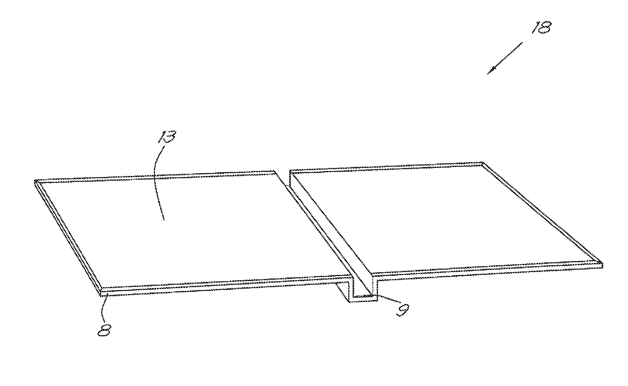
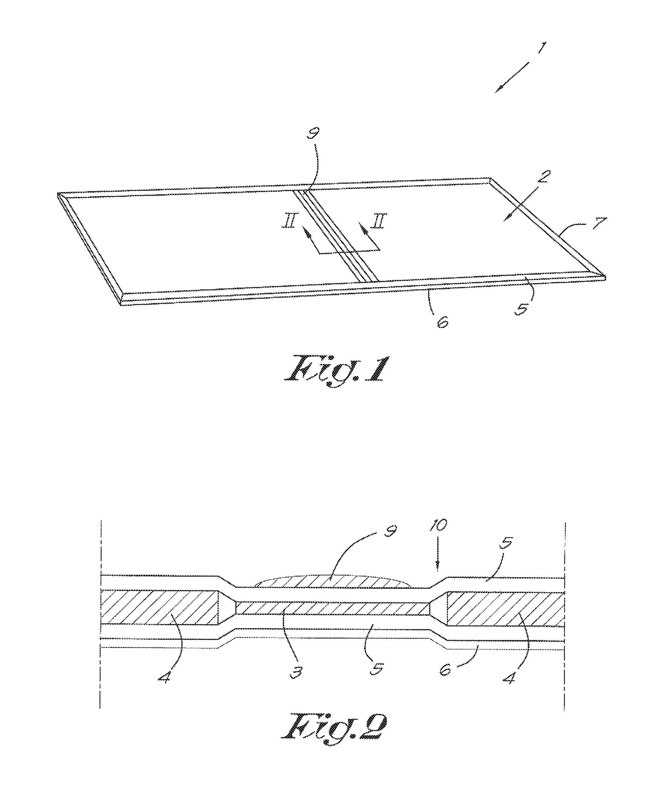
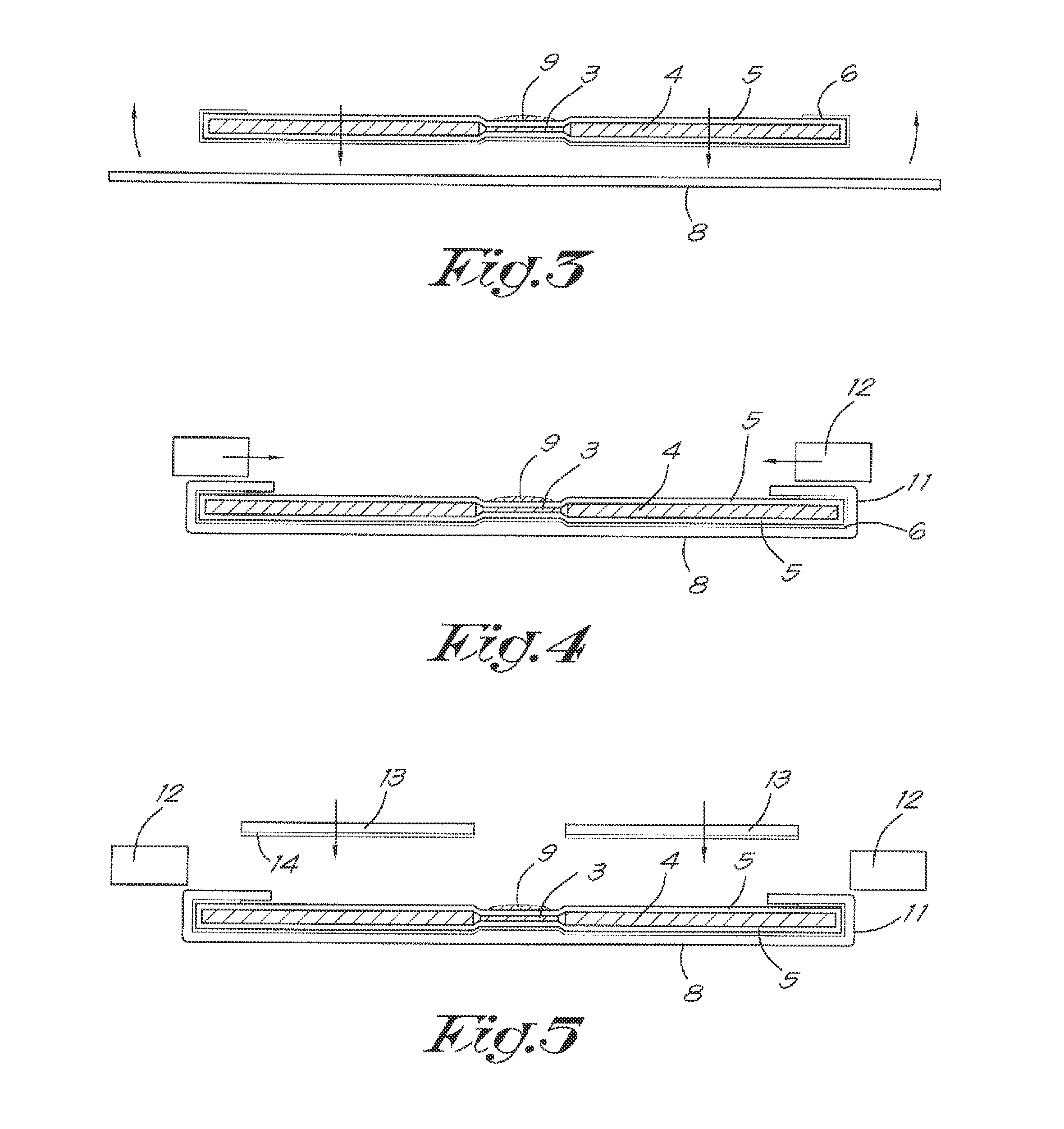
[0043]FIGS. 1 and 2 schematically represent a binding element 1 applied in a method according to the invention, which binding element 1 is a semi-finished product which is mainly composed of a flat support 2 formed of a central flat strip 3 and two flat plates 4 on either side of the above-mentioned strip 3.

[0044]The central strip 3 is thereby designed to form the back of the binding file later on, and the two plates 4 are designed to form the end leaves.

[0045]This support 2 is provided with a covering 5 provided over or around said support 2, and the covering 5 is provided with a layer of hotmelt glue 6 on the outside, extending on the outer surface of one side of the binding element 1 and on the edges 7 of the opposite side of the binding element 1.

[0046]The melting temperature of the hotmelt glue 6 is preferably not too high, such that a little heating is sufficient to liquidize the glue.

[0047]In practice, a hotmelt glue 6 is used whose melting temperature is lower than the tempe...


PUM


Abstract

Method for manufacturing a binding file by using a binding element (1) includes providing a printed outer covering (8) and subsequently placing the flat element (1) on the covering (8) with the glue (6) facing down, and folding back the covering (8) at the edges (11) over the edges (7) of the element (1). The edges (11) are locally heated and cooled down to temporarily fix the covering (8), after which the whole is heated, pressed and cooled down again and to transform the strip (3) so as to form a U-shaped back.

Description

CROSS REFERENCE TO RELATED APPLICATIONS[0001]This application is a division of copending application Ser. No. 13 / 144,997 filed on Jul. 18, 2011; which is the 35 U.S.C. 371 national stage of International application PCT / IB2010 / 000090 filed on Jan. 19, 2010; which claims priority to BE application 20090036 filed on Jan. 29, 2009. The entire contents of each of the above-identified applications are hereby incorporated by reference.BACKGROUND OF THE INVENTION[0002]1. Field of the Invention[0003]The present invention concerns a method for manufacturing a binding file using a binding element.[0004]In particular, the invention aims to produce a binding file formed of a U-shaped back and two end leaves for binding a bundle of leaves such as for example leaves with photos in order to make a photo album.[0005]2. Discussion of the Related Art[0006]Binding elements provided with an outer covering are already known, whereby the outer covering, before the bundle is being bound, has already been ...

Claims


Application Information

Patent Timeline
IPC IPC(8): B32B38/00
CPCB32B38/1841B32B2037/1223B32B2307/718B32B2317/122B32B2317/127B42C7/00Y10T156/1051B42D3/002B32B38/0012Y10T428/2817Y10T428/24628Y10T428/24802Y10T428/24612B42C7/006
Inventor PELEMAN, GUIDO
Owner UNIBIND
Why Eureka
Try Eureka