Diesel exhaust fluid and fuel fill system

a technology of diesel exhaust fluid and fuel fill system, which is applied in the direction of machines/engines, mechanical equipment, transportation and packaging, etc., can solve the problems of corrosive effects and insecure placement of the fuel tank filler tube, and achieve the effect of optimizing space use and access and corrosive effects

Active Publication Date: 2013-11-07
DEERE & CO
View PDF5 Cites 28 Cited by
  • Summary
  • Abstract
  • Description
  • Claims
  • Application Information

AI Technical Summary

Benefits of technology

[0004]Disclosed is a DEF tank having a DEF tank filler tube in proximity to a fuel tank filler tube. Both DEF and fuel filler tubes may be located for ease of access as well as simultaneous access. The DEF tank filler tube may be located in proximity to the DEF tank to avoid DEF crystallization and freezing en route to the DEF tank. To optimize spa

Problems solved by technology

On many work vehicles such as, for example, loaders, conventional fuel systems allow fuel tanks to be conveniently and securely located on the vehicle but frequently filler tubes for the tanks are not securely located.
Suc

Method used


Image

  • Diesel exhaust fluid and fuel fill system
  • Diesel exhaust fluid and fuel fill system
  • Diesel exhaust fluid and fuel fill system

Examples


Embodiment Construction

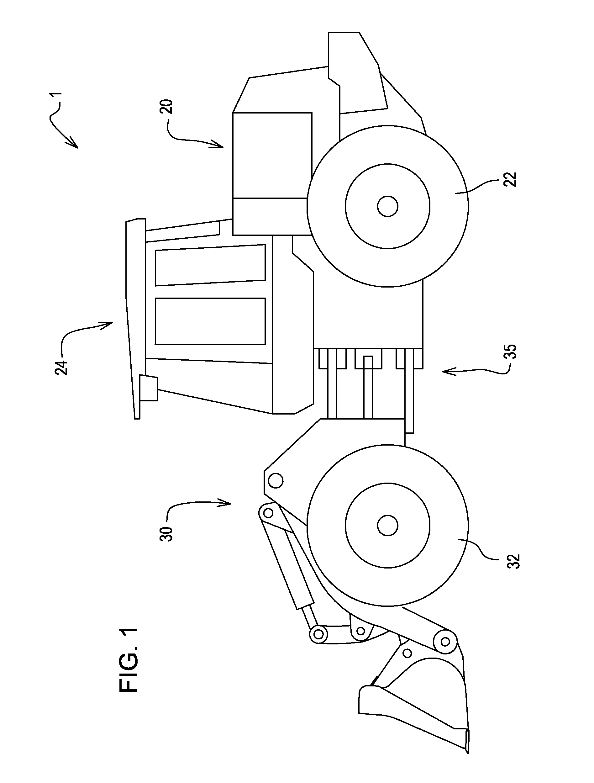
[0017]FIG. 1 illustrates a work vehicle 1 in which the invention may be used. The particular work vehicle illustrated in FIG. 1 is an articulated four wheel drive loader having a body which includes a rear body portion 20 pivotally connected to a front body portion 30 by vertical pivots 35. The loader 1 may be steered by pivoting of the front body portion 30 relative to the rear body portion 20 in a manner well known in the art. The rear and front body portions 20 and 30 are respectively supported on rear drive wheels 22 and front drive wheels 32. An operator's station 24 is provided on the rear body portion 20 and may be generally located above the vertical pivots 35. The rear and front drive wheels 22 and 32 may propel the vehicle along the ground and are powered in a manner well known in the art.

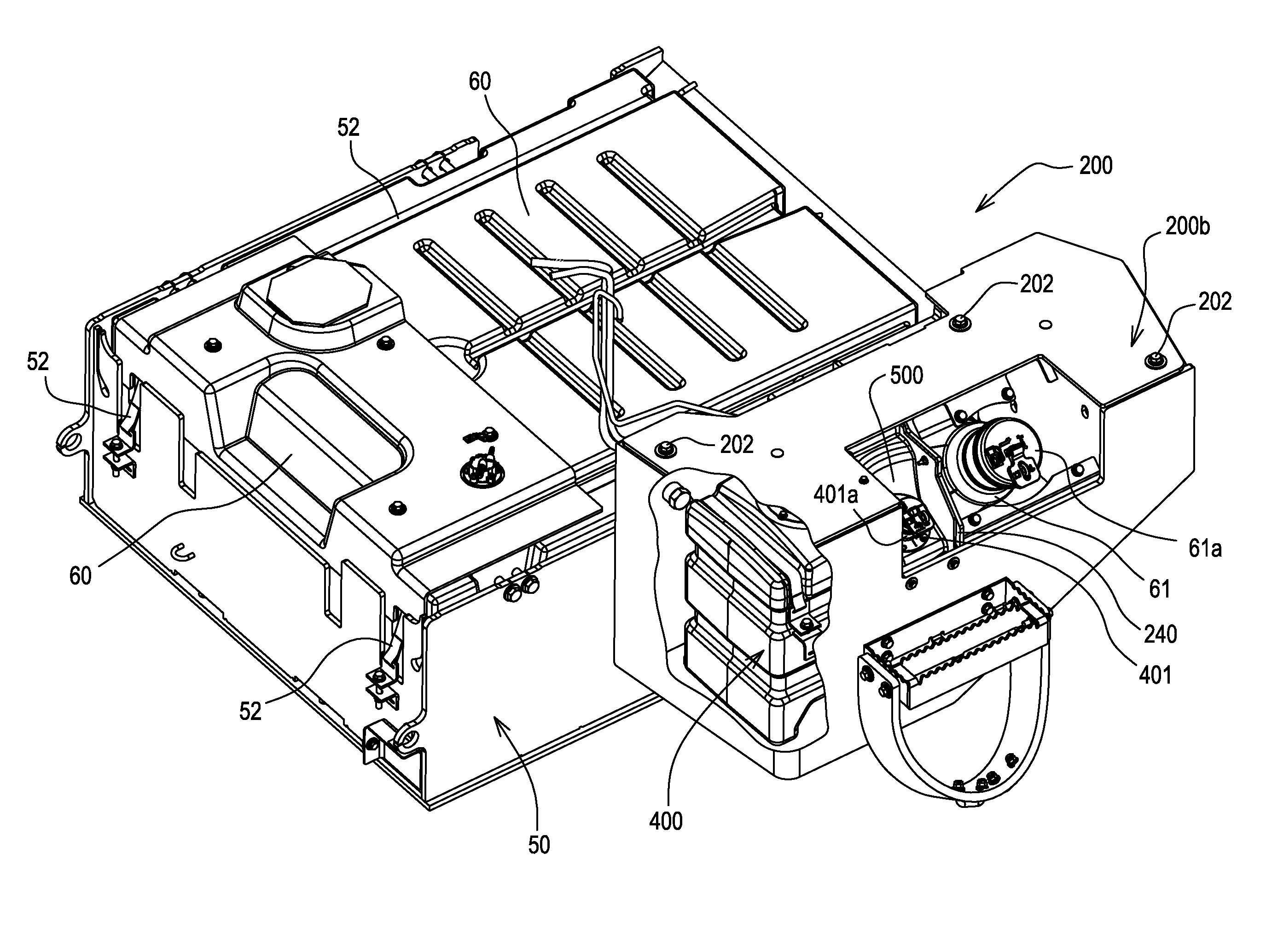
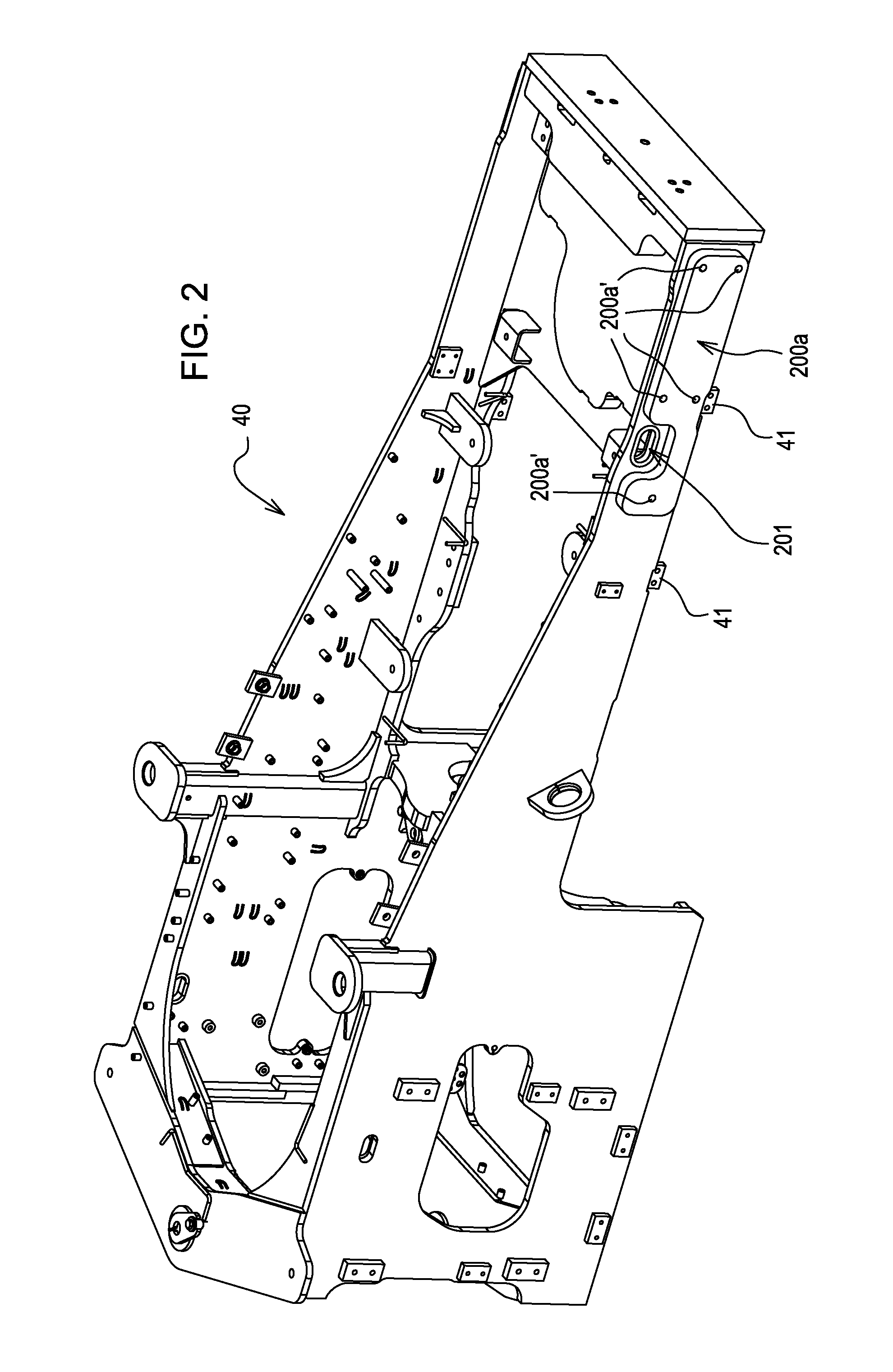
[0018]FIG. 2 illustrates a rear frame 40 for the articulated loader 1 of FIG. 1. Mounted on the rear frame 40 at mounting tabs 41 via screws 51 may be a cradle 50 for shielding and positi...


PUM


Abstract

A system including a DEF tank and a fuel tank arranged in a portion of a vehicle to give that portion multiple structural functions. The system may be arranged to form a part of a counterweight on a work vehicle.

Description

FIELD OF THE INVENTION[0001]The invention relates to locations for fuel tanks and diesel exhaust fluid (DEF) tanks on work vehicles as well as related fill locations. More specifically, it relates to a structure, system and method of increasing the reliability and convenience of fuel systems in work vehicles by efficiently locating the fuel and DEF tanks and conveniently locating and protecting their respective fill ports.BACKGROUND OF THE INVENTION[0002]On many work vehicles such as, for example, loaders, conventional fuel systems allow fuel tanks to be conveniently and securely located on the vehicle but frequently filler tubes for the tanks are not securely located. Further, in order to meet modern emissions requirements, many diesel powered work vehicles employ systems that may use additional fluids to treat engine exhaust to significantly reduce nitrogen oxide levels.[0003]One such system is selective catalytic reduction (SCR) which includes dosing a reductant (generically, die...

Claims


Application Information

Patent Timeline
IPC IPC(8): B65D25/04
CPCF01N2590/08F01N2610/1413B60K2015/0467B60K13/04B60K15/04B60K15/05B60K2015/0487B60Y2200/415B60K2015/0474E02F9/0833E02F9/0841E02F9/0883E02F9/0891E02F9/18
Inventor KLAUER, AARON S.PATIL, NITIN N.
Owner DEERE & CO
Why Eureka
Try Eureka