
Terminal and method for iris scanning and proximity sensing

a technology of proximity sensing and terminals, applied in the direction of acquiring/recognizing eyes, static indicating devices, instruments, etc., can solve the problems of insufficient application of iris scanning to terminals in korea and elsewhere, the importance of information is on the increase, and the security technology applied to terminals is also getting sophisticated

Active Publication Date: 2013-11-07
SAMSUNG ELECTRONICS CO LTD
View PDF3 Cites 44 Cited by
  • Summary
  • Abstract
  • Description
  • Claims
  • Application Information

AI Technical Summary

Benefits of technology

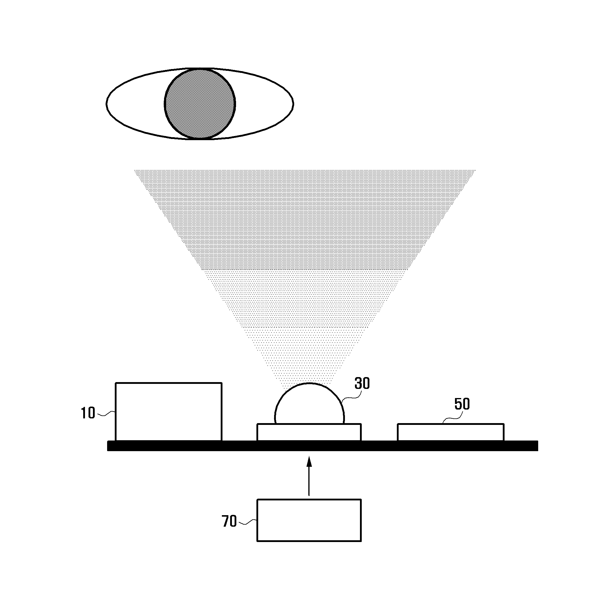
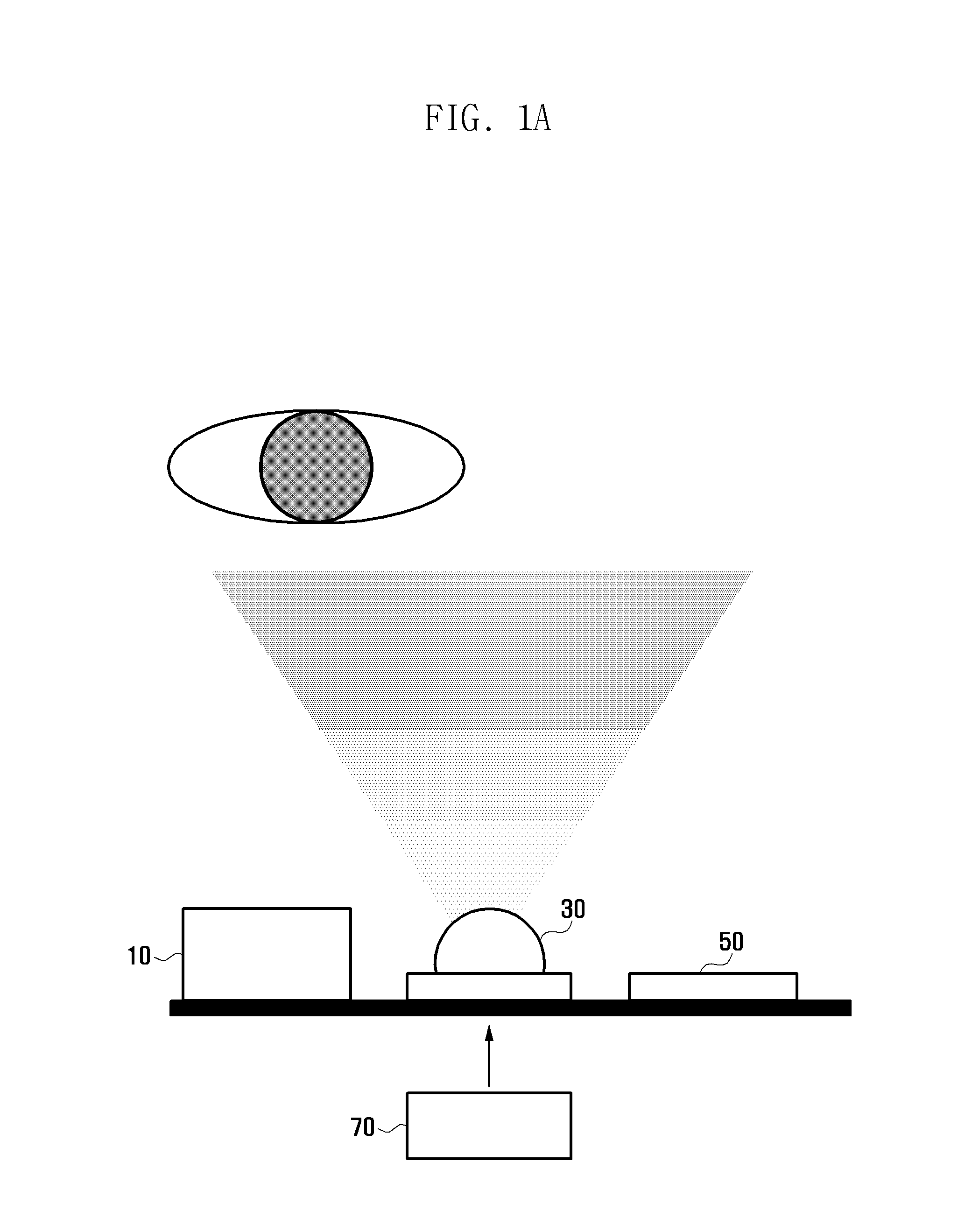
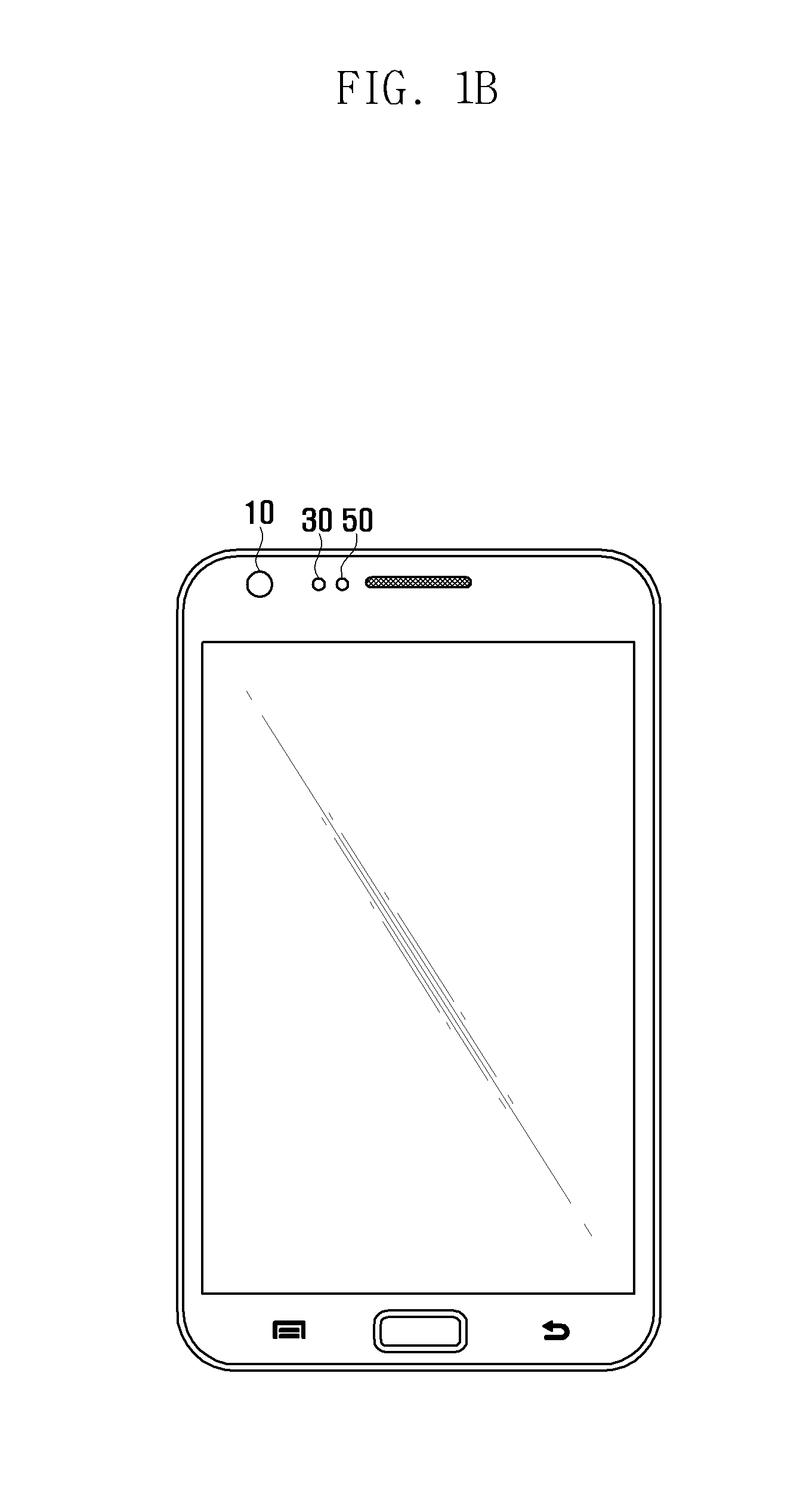
The present invention aims to improve iris scanning speed using a terminal's built-in proximity sensor without the need for a separate infrared ray illuminator. The technical effect is increased efficiency in iris scanning without the need for additional equipment in the terminal.

Problems solved by technology

Further, as a terminal, such as a portable terminal, a mobile device, a cell phone, or other electronic devices, gets rapidly sophisticated, the amount of information stored in the terminal increases, the importance of information is on the increase, and a security technology applied to the terminal is also getting sophisticated.
However, despite all such advantages, iris scanning is not being widely applied to terminals in Korea and elsewhere.
This is partly because of the costs of iris scanning technology in the prior art, but is also because of the scanning rate problem.
However, in the case of other people, including Asian people, many Asians do not have sufficient melanin pigments in their eyes, and thus infrared rays need to be stably secured.
However, having a separate built-in infrared ray illumination for iris scanning would make it difficult for the terminal to be lighter and smaller.

Method used


Image

  • Terminal and method for iris scanning and proximity sensing
  • Terminal and method for iris scanning and proximity sensing
  • Terminal and method for iris scanning and proximity sensing

Examples


Embodiment Construction

[0024]Exemplary embodiments of the present invention are described with reference to the accompanying drawings in detail. The same reference numbers are used throughout the drawings to refer to the same or like parts. Detailed descriptions of well-known functions and structures incorporated herein may be omitted to avoid obscuring the subject matter of the present invention.

[0025]The present invention may, however, be embodied in many different forms and should not be construed as limited to the exemplary embodiments set forth herein. In addition, terms described herein, which are defined with reference to the functions of the present invention, may be implemented differently depending on a user or operator's intention and practice. Therefore, the terms should be understood on the basis of the disclosure throughout the specification. The principles and features of this invention may be employed in varied and numerous embodiments without departing from the scope of the invention.

[002...


PUM


Abstract

A method of iris scanning and proximity sensing includes: receiving selection information of an operation mode; sensing an iris including emitting light having an amount of light of a first level, and photographing an iris using the emitted light if a selected operation mode is a iris scanning mode; sensing a proximity including emitting light having an amount of light of a second level, and sensing information on whether an object has approached using the emitted light if the selected operation mode is a proximity sensing mode; and recognizing the iris using the photographed iris image, and performing a function according to the sensed information on whether the object has approached, and the first level has a value higher than the value of the second level.

Description

CLAIM OF PRIORITY[0001]This application claims, pursuant to 35 U.S.C. §119(a), priority to and the benefit of the earlier filing date of a Korean patent application filed on May 4, 2012 in the Korean Intellectual Property Office and assigned Serial No. 10-2012-0047311, the entire disclosure of which is hereby incorporated by reference.BACKGROUND OF THE INVENTION[0002]1. Field of the Invention[0003]The present invention relates to a terminal and method for iris scanning and proximity sensing, and more particularly, to a terminal capable of increasing the iris scanning rate by sharing light emitting illumination needed for proximity sensing and light emitting illumination needed for iris scanning, and a method of iris scanning and proximity sensing.[0004]2. Description of the Related Art[0005]Iris scanning is used to collect information of characteristics of respective attributes of irises of people and use the information in authentication technology for security. The iris has unique...

Claims


Application Information

Patent Timeline
IPC IPC(8): G06F3/01G06V10/143
CPCG06F3/011G06F3/013G06V40/19G06V10/143G06V10/10G06V10/40
Inventor YOON, SUNGJIN
Owner SAMSUNG ELECTRONICS CO LTD
Learn More