
Touch panel, touch display panel and touch display apparatus

a touch display and touch technology, applied in the field of touch panels, can solve the problems of reducing the size of the decoration frame, unable to narrow the decoration frame, and unable to quickly conduct the mass electrostatic discharge accumulated on the guard ring for preventing the touch panel from being damaged, so as to improve the ability of electrostatic discharge protection and rapid conduct the electrostatic discharge

Inactive Publication Date: 2013-11-07
AU OPTRONICS CORP
View PDF7 Cites 39 Cited by
  • Summary
  • Abstract
  • Description
  • Claims
  • Application Information

AI Technical Summary

Benefits of technology

The invention provides a touch panel with a slim border design and good electrostatic discharge protection. The reflective protecting electrode covers the noise of the external environment, so a guard ring is not needed. The touch panel has a ground state through the electrostatic discharge protecting device, which helps to protect against static charges. Overall, the touch panel has a slimmer and more aesthetically pleasing design while still being effective at protecting against static charges.

Problems solved by technology

However, the guard ring may take up a large area of the decoration region, thus the decoration frame of the touch panel cannot be narrowed down due to the fabricating of guard ring.
On the other hand, if the touch panel is without the guard ring, the electrostatic discharge protecting device cannot be disposed in the narrowed decoration frame for reducing electrostatic discharge.
Additionally, how to rapidly conduct the mass electrostatic discharge accumulated on the guard ring for preventing the touch panel from damaged becomes an important issue.

Method used


Image

  • Touch panel, touch display panel and touch display apparatus
  • Touch panel, touch display panel and touch display apparatus
  • Touch panel, touch display panel and touch display apparatus

Examples


Embodiment Construction

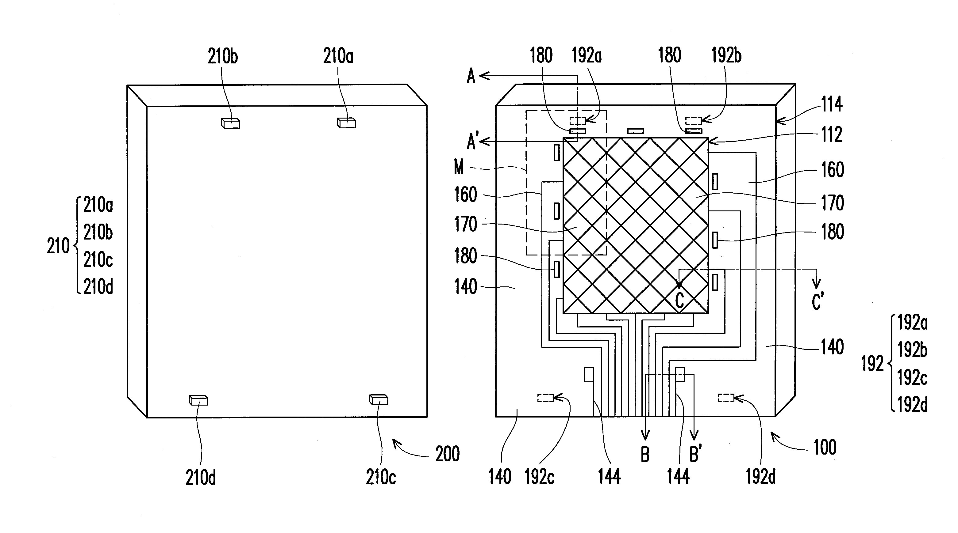
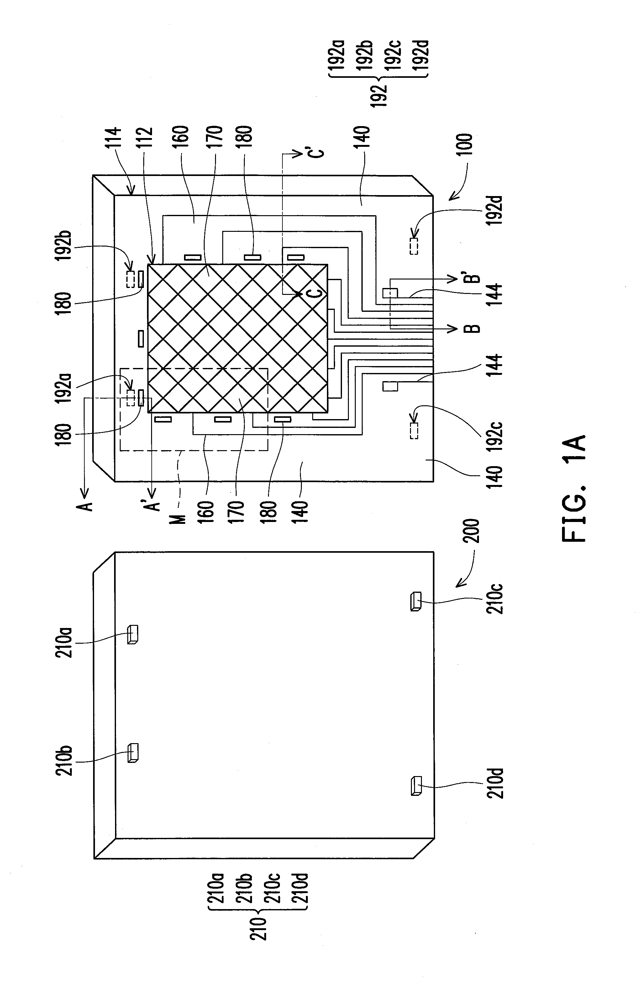
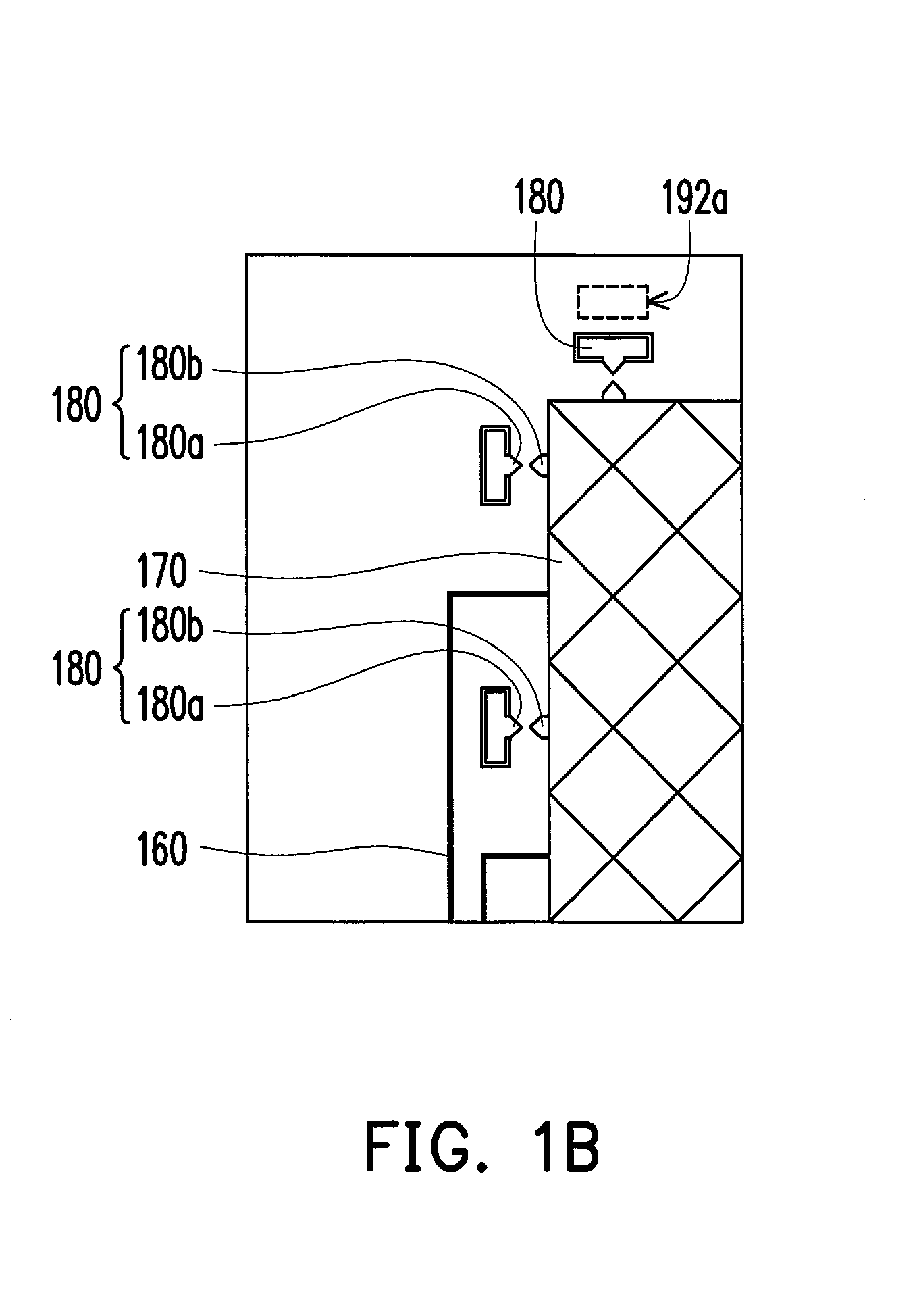
[0026]FIG. 1A schematically shows a perspective view of a touch panel and a casing assembly according to a first embodiment of the present invention, wherein some film layers are omitted in FIG. 1A. FIG. 1B is a partially enlarged schematic view of portion M of FIG. 1A. FIG. 2A schematically shows a cross-sectional view of the touch panel according to the first embodiment of the present invention. In addition, FIG. 2A is a cross-sectional view of a touch panel along sectioning lines A-A′, B-B′ and C-C′ of FIG. 1A.

[0027]Referring to FIG. 1A, FIG. 1B and FIG. 2A, the touch panel 100a of the embodiment is capable of assembling to a casing assembly 200, and the casing assembly 200 has at least one conductive protrusion 210. The touch panel 100a includes a substrate 110, a decoration pattern layer 120, a touch sensing device 170, a reflective protecting electrode 140, an electrostatic discharge protecting device 180, a plurality of signal connecting lines 160, an insulating layer 150 and...


PUM


Abstract

A touch panel capable of assembling to a casing assembly having a conductive protrusion is provided. The touch panel includes a substrate, a decoration pattern layer, a touch sensing device, a reflective protecting electrode, an electrostatic discharge protecting device, a plurality of signal connecting lines, an insulating layer and a protection layer. The decoration pattern layer is located in a periphery region of the substrate and overlapped with the reflective protecting electrode. The electrostatic discharge protecting device is connected to the touch sensing device and the reflective protecting electrode to transmit electrostatic charges to the reflective protecting electrode. The signal connecting lines are overlapped with the decoration pattern layer and electrically connected to the touch sensing device. The protection layer has an opening to expose a portion of the reflective protecting electrode such that the reflective protecting electrode is electrically connected to the conductive protrusion through the opening.

Description

CROSS-REFERENCE TO RELATED APPLICATION[0001]This application claims the priority benefit of Taiwan application serial no. 101116213, filed on May 7, 2012. The entirety of the above-mentioned patent application is hereby incorporated by reference herein and made a part of this specification.BACKGROUND OF THE DISCLOSURE[0002]1. Field of the Disclosure[0003]The present invention generally relates to a touch panel, and more particularly, to a touch panel of a touch display apparatus.[0004]2. Description of Related Art[0005]In recent years touch sensing technologies have been widely applied to all sorts of multi-media electronic products, especially the portable mobile products, for example mobile phones, electronic books (E-books), tablet PC or the like. The touch sensing technologies are used as inputting means and tend to replace conventional input devices such as keyboards and mice. This touch inputting technology not only enhances the convenience, but also becomes a popularized huma...

Claims


Application Information

Patent Timeline
IPC IPC(8): G06F3/044G06F3/041
CPCG06F3/044G06F3/0443G06F3/0446
Inventor LIN, CHENG-HSINGKUO, WEI-HUNGCHOU, SHIH-POHUANG, YEN-HENG
Owner AU OPTRONICS CORP
Learn More