
Image display apparatus and image display method

a technology of image display and image, applied in the field of image display apparatus and image display method, can solve the problems of low light use efficiency of color filter liquid crystal display apparatus, and the generation of color breakage in field sequential color technique, so as to reduce the generation of color breakage

Active Publication Date: 2013-11-07
SHARP KK
View PDF4 Cites 24 Cited by
  • Summary
  • Abstract
  • Description
  • Claims
  • Application Information

AI Technical Summary

Benefits of technology

The present invention is related to an image display apparatus operating in the field sequential mode, which can reduce the generation of color breaks when displaying images that suffer from strong color breaks in a localized fashion. The technical effect of the invention is to effectively reduce the generation of color breaks by controlling the state of the light source during the extension subframe period, in view of the color break strength of a color mixed component with the highest color break strength being contained more in the light output from the light source. The color break strength is determined in view of two factors related to the noticeability of the color break strength, namely its effectiveness in visually recognizing the color break and the strength of the color break in a localized fashion. Overall, the invention improves the quality of displayed images and enhances the user's experience.

Problems solved by technology

Since about two-thirds of backlight rays irradiating a liquid crystal panel are absorbed by the color filter, a color-filter liquid crystal display apparatus has a problem of low light use efficiency.
However, the field sequential color technique suffers from a problem of a generation of color break. FIG. 27 illustrates the generation principle of the color breaking.

Method used


Image

  • Image display apparatus and image display method
  • Image display apparatus and image display method
  • Image display apparatus and image display method

Examples


first embodiment

1.1 General Configuration and Operation Description

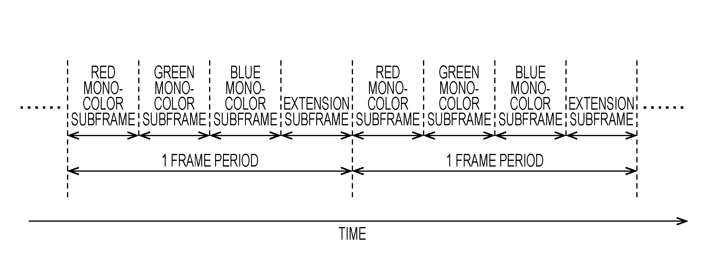
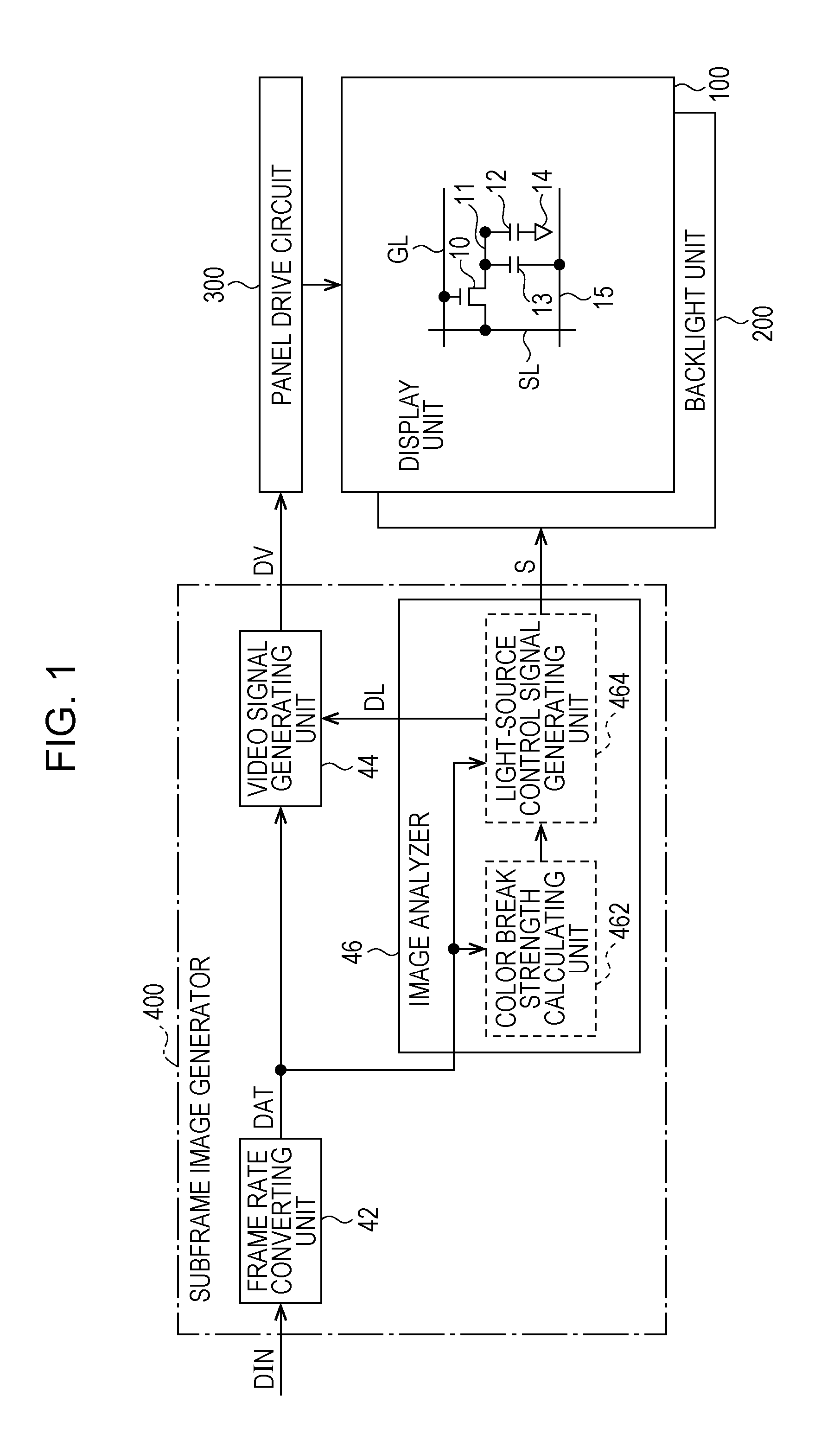
[0071]FIG. 1 is a block diagram illustrating a general configuration of a liquid crystal display apparatus of a first embodiment of the present invention. The liquid crystal display apparatus includes a display unit 100, a backlight unit 200, a panel drive circuit 300, and a subframe image generator 400. The subframe image generator 400 includes a subframe rate converting unit 42, a video signal generating unit 44, and an image analyzer 46. The image analyzer 46 includes a color break strength calculating unit 462, and a light-source control signal generating unit (light-source controller) 464. The backlight unit 200 includes three-color LEDs of red (R), green (G), and blue (B) as backlights (light sources), and an LED control circuit that controls the states (light-on state / light-off state) of the LEDs. A plurality of LEDs are typically arranged for each color.

[0072]The display unit 100 includes a plurality of source bus lines (vid...

second embodiment

2. Second Embodiment

2.1 Configuration and Operation

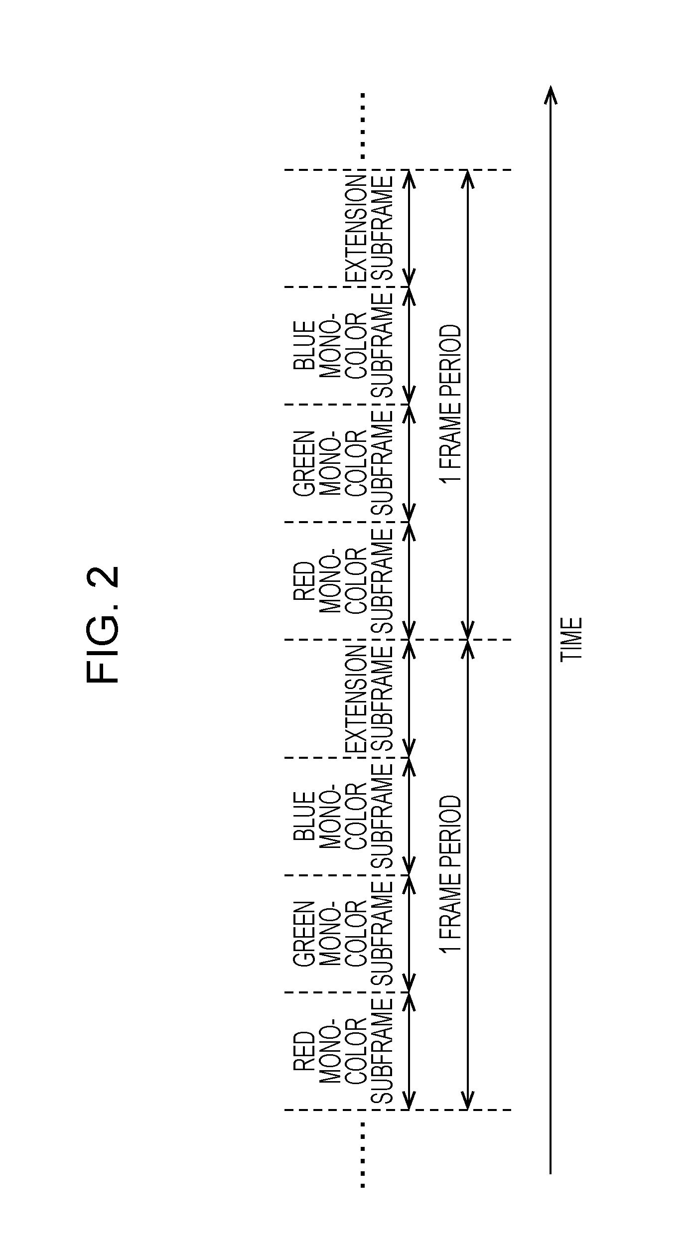
[0104]A second embodiment remains unchanged from the first embodiment in terms of the configuration of the liquid crystal display apparatus and the structure of the one frame period, and the discussion thereof is omitted herein (see FIG. 1 and FIG. 2). The determination method of the first pixel region, the determination method of the second pixel region, and the determination method of the color break strength are identical to those in the first embodiment, and the discussion thereof is omitted herein.

[0105]If the color break strengths of all the color mixed components contained in the light output from the backlight unit are lower than a predetermined level (hereinafter referred to as a “comparative level”) in the present embodiment, the light-source control signal generating unit 464 outputs a light-source control signal S so that the LEDs of all the colors shift to the light-off state during the extension subframe period as illu...

third embodiment

3. Third Embodiment

3.1 Summary

[0110]Each of the above embodiments, only one extension subframe period is arranged in one frame period. However, the color break strength may be visibly recognized in a plurality of color mixed components depending on the target image. For example, there are present within the target image a region Z1a containing a high percentage of yellow components and a region Z1b containing a high percentage of cyan components as illustrated in FIG. 22. In such a case, even if a yellow image is displayed during the extension subframe period (one extension subframe is arranged within one frame period), a color break strength caused by the cyan component occurs. According to the present embodiment, two extension subframe periods (a first extension subframe and a second extension subframe) are arranged within one frame period as illustrated in FIG. 23. The configuration of the liquid crystal display apparatus remains unchanged from that of the first embodiment, and t...


PUM


Abstract

An image display apparatus operates in field sequence mode which effectively reduces the generation of color break. A color break strength calculating unit determines a color break strength that indicates the noticeability of the generation of the color break. A light-source signal generating unit controls each light source so that as the color break strength of a color mixed component having the highest color break strength is higher, the color mixed component is contained more in light output from a light-source unit during the extension subframe period. If there is present a first pixel region as an area including one or more pixel formation regions where an image containing the component of interest is displayed, the color break strength of the component of interest increases more as a magnitude of the component of interest is larger in the first pixel region.

Description

TECHNICAL FIELD[0001]The present invention relates to an image display apparatus and an image display method, and more in detail, a technique of controlling the generation of color break in an image display apparatus that operates in a field sequential mode.BACKGROUND ART[0002]Many of the liquid crystal display apparatuses that display a color image include a color filter that allows light rays of red (R), green (G), and blue (B) to pass through respectively three sub pixels into which one pixel is divided. Since about two-thirds of backlight rays irradiating a liquid crystal panel are absorbed by the color filter, a color-filter liquid crystal display apparatus has a problem of low light use efficiency. For this reason, a field-sequential liquid display apparatus that displays a color image without using the color filter gains attention.[0003]In accordance with the field sequential technique, a display period (1 frame period) of one screen is divided into three subframe periods. Th...

Claims


Application Information

Patent Timeline
Patent Type & Authority Applications(United States)
IPC IPC(8): G09G3/36
CPCG09G3/3648G09G2310/0235G09G3/3607G09G2320/064G09G2320/0242
Inventor ISHIHARA, TOMOYUKI
Owner SHARP KK
Learn More