
Method and apparatus for finding a motion vector

a motion vector and motion detection technology, applied in signal generators with optical-mechanical scanning, color televisions with bandwidth reduction, etc., can solve the problems of high-level motion estimation problems, cumbersome real-time video data processing, and computational complexity of video data processing

Active Publication Date: 2013-11-07
CELLCO PARTNERSHIP INC
View PDF1 Cites 7 Cited by
  • Summary
  • Abstract
  • Description
  • Claims
  • Application Information

AI Technical Summary

Benefits of technology

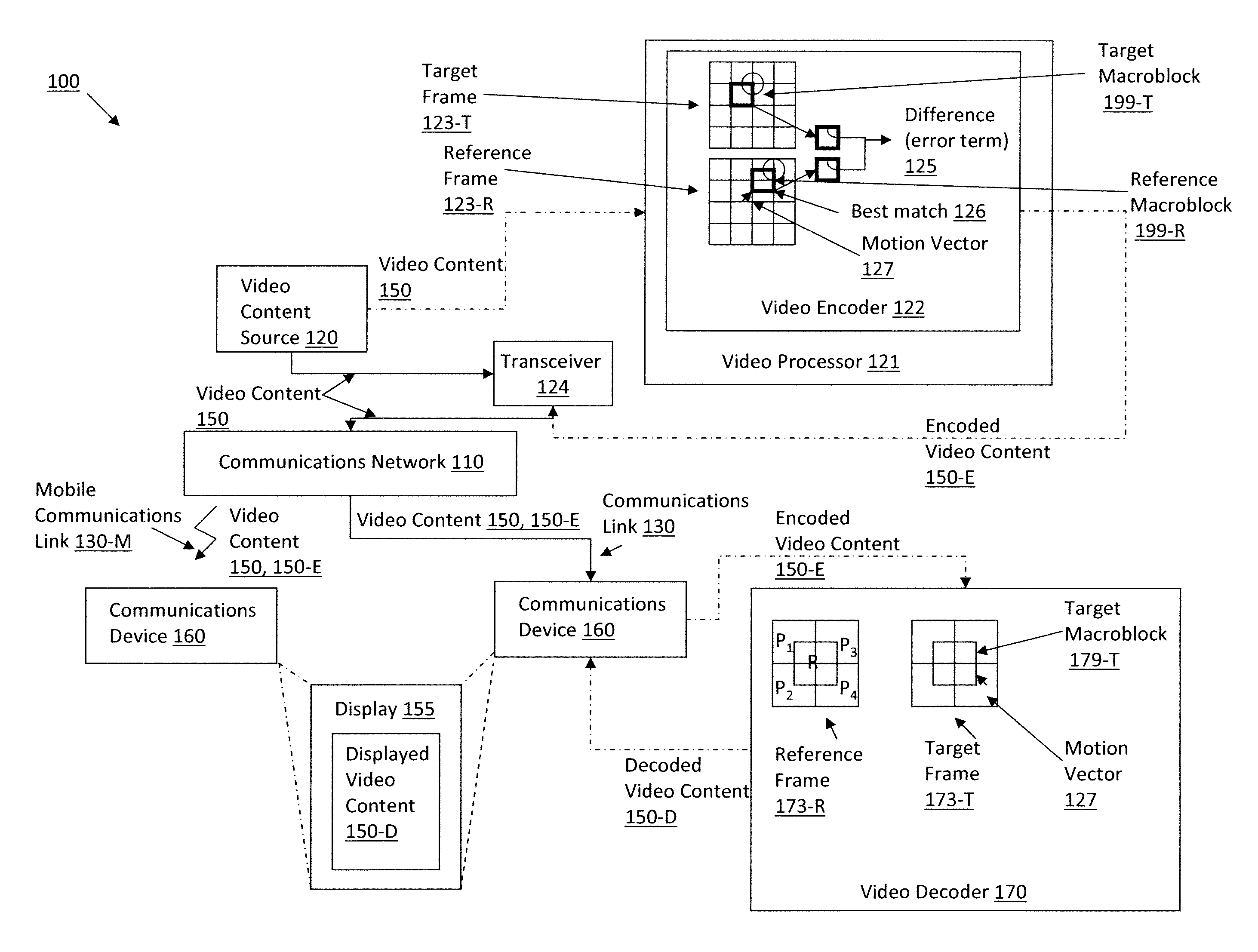
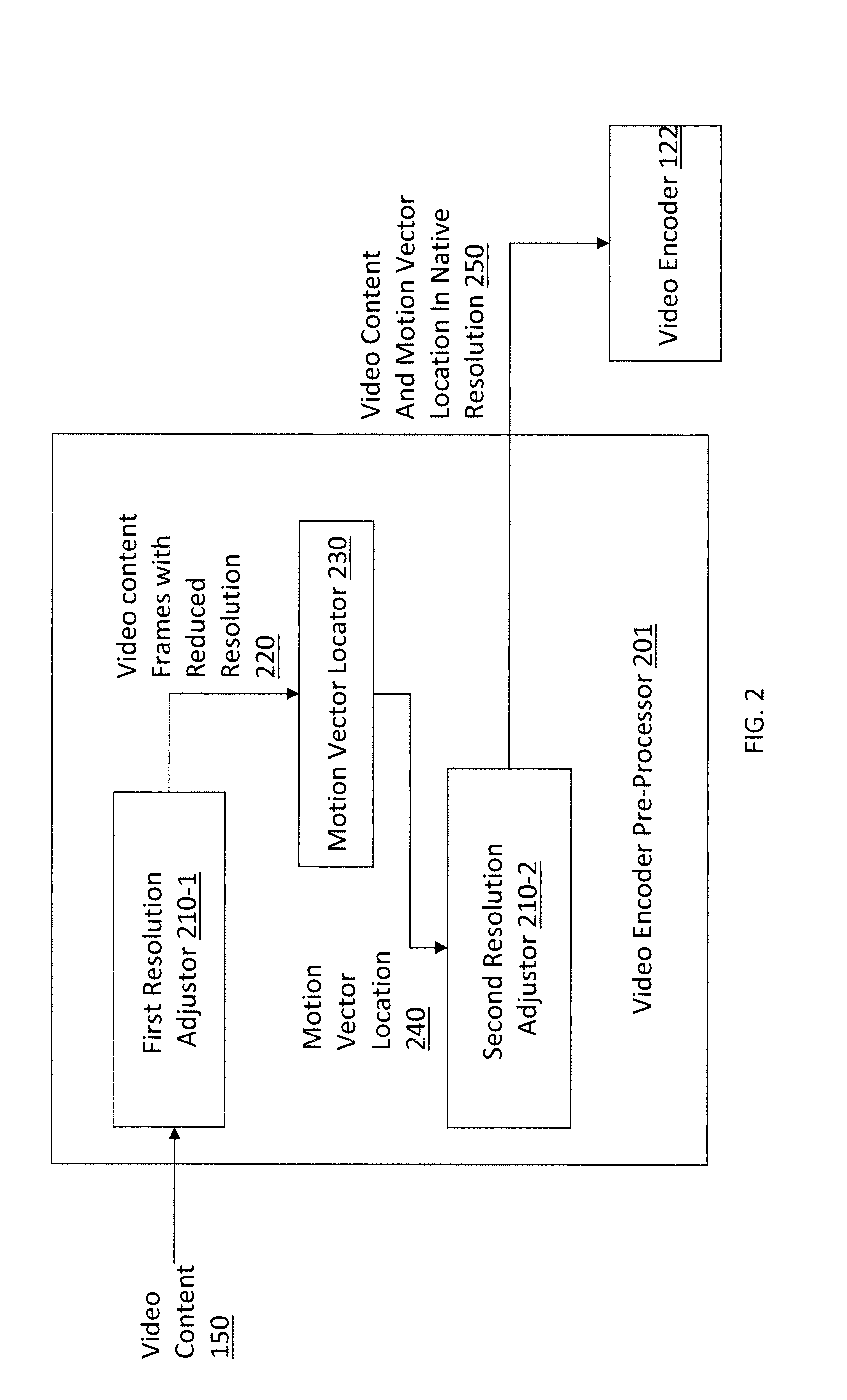
The patent text describes a method and system for determining motion vectors in video data. Motion vectors are used to describe the transformation of images from one frame to another. The process of finding motion vectors can be time-consuming and resource-intensive, so the patent proposes a solution to speed up the process by reducing the resolution of the reference frame and target frame and comparing them using a sliding window. The technical effect of this approach is to improve the efficiency and speed of video processing by reducing the complexity of motion vector estimation.

Problems solved by technology

Processing video data may be a computationally complex task due to the high data rates involved.
Such data sizes and rates may stress networks and make real-time processing of video data cumbersome.
Motion estimation is a highly ill-posed problem since the frames (images) are obtained from projection of a three-dimensional (3-D) medium onto a 2-D plane.
This renders the problem of searching for and determining the motion vector complex and computationally intensive.
Available schemes for finding motion vectors often approach this problem by initializing a search at a location, such as the (0,0) location of a macroblock, and searching for the motion vector in the entire macroblock, thereby consuming a significant amount of power and central processing resources.

Method used


Image

  • Method and apparatus for finding a motion vector
  • Method and apparatus for finding a motion vector
  • Method and apparatus for finding a motion vector

Examples


Embodiment Construction

[0009]In the following detailed description, numerous specific details are set forth by way of examples in order to provide a thorough understanding of the relevant teachings. However, it should be apparent to those skilled in the art that the present teachings may be practiced without such details. In other instances, well known methods, procedures, components, and / or circuitry have been described at a relatively high-level, without detail, in order to avoid unnecessarily obscuring aspects of the present teachings.

[0010]It is understood that other configurations of the subject technology will become readily apparent to those skilled in the art from the following detailed description, wherein various configurations of the subject technology are shown and described by way of illustration. As will be realized, the subject technology is capable of other and different configurations and its several details are capable of modification in various other respects, all without departing from...


PUM


Abstract

Methods and related systems for encoding video streams are described. Reference and target frames of a video stream are scaled to reduce their resolution. A sliding window is used to compare the reduced resolution reference and target frames and identify blocks, outlined by a sliding window, that include similar content. A motion vector indicating the motion of the identified similar content is determined. Once the motion vector is determined, the reference and target frames are restored to their native resolution and a translated location for the motion vector is identified in the restored frames. The translated location of the motion vector may be used in encoding the frames of the video stream.

Description

BACKGROUND[0001]Processing video data may be a computationally complex task due to the high data rates involved. For example, television quality video may require up to 27 Mega Bytes per second. Such data sizes and rates may stress networks and make real-time processing of video data cumbersome. Accordingly, video data is often stored in a compressed format.[0002]Motion vectors are often used for motion estimation in video compression to describe transformation from one two-dimensional (2-D) image to another 2-D image. Motion vectors may be used to represent transformation of a whole image (e.g., in a global motion estimation problem), specific parts of the image (e.g., blocks, or patches), or individual pixels of the image.[0003]Motion estimation is a highly ill-posed problem since the frames (images) are obtained from projection of a three-dimensional (3-D) medium onto a 2-D plane. This renders the problem of searching for and determining the motion vector complex and computationa...

Claims


Application Information

Patent Timeline
IPC IPC(8): H04N7/26
CPCH04N19/53H04N19/132H04N19/172H04N19/61
Inventor GUDURU, VIJAYKRISHNA P.
Owner CELLCO PARTNERSHIP INC
Learn More