Digital mask-image-projection-based additive manufacturing that applies shearing force to detach each added layer

a technology of additive manufacturing and digital mask, applied in additive manufacturing, auxillary shaping apparatus, manufacturing tools, etc., can solve the problems of inability to meet the needs of digital material fabrication, limited fdm process, and limited nozzle size and minimum nozzle size,

Active Publication Date: 2013-11-07
UNIV OF SOUTHERN CALIFORNIA
View PDF0 Cites 537 Cited by
  • Summary
  • Abstract
  • Description
  • Claims
  • Application Information

AI Technical Summary

Benefits of technology

[0033]Before one instance of the relative movement, the translation stage may be in a first horizontal position with respect to the vat. After the one instance of the relative movement, the translation stage may be in a second horizontal position with respect to the vat that is substantially different than the horizontal first position. The process controller may, while in both the first and the second horizontal positions, causes the mask image projection system to project a two-dimensional image of the highest un-solidified layer of the three-dimensional object through the bottom of the vat and into the liquid resin, thereby causing at least a portion of the liquid resin to solidify in the shape of the two-dimensional image.

Problems solved by technology

Such a process can have inherent limitations on the selection of base materials, since the jetted liquid may need to have certain viscosity and curing temperature properties in order to be jetted.
However, the FDM process may have limitations on its minimum nozzle size and may be relatively slow.
Hence, FDM may not be suitable for digital material fabrication.
However, accurate material feeding and recoating may be required by the digital material fabrication, but may be difficult to integrate into an SLS process.
However, based on the lengthy process of manually changing the materials, the system may be limited to simple 2.5D microstructures.
A challenge in the use of multiple materials in SL may be how to manage material contamination between changing different materials used in the fabrication process.
Due to the deep vat, draining and cleaning the current resin before changing to another resin vat may take a long time and may lead to significant material waste.
Even though the approach may be able to reduce the material changeover efforts, it may not be a general approach, especially for digital material fabrication in which different materials may be interlocked with each other.
Hence, the bottleneck for achieving a fast building speed may be the spreading of liquid resin into uniform thin layers.
However, such recoating methods may take over a minute, which may limit the building speed of the MIP-SL process.
The solidified material may adhere strongly to the corresponding rigid or semi-rigid transparent solidification substrate, causing the object to break or deform when the build platform and vat are pulled apart during the building process.
However, over-curing can lead to poor surface quality and inaccurate dimensions.
Experiments indicate that, for a square of 60×60 mm, the pulling force to separate the part from the film can be greater than 60 N. Such a large attachment force between the cured layer and the vat can be a key challenge in the development of the bottom-up projection based MIP-SL system.

Method used


Image

  • Digital mask-image-projection-based additive manufacturing that applies shearing force to detach each added layer
  • Digital mask-image-projection-based additive manufacturing that applies shearing force to detach each added layer
  • Digital mask-image-projection-based additive manufacturing that applies shearing force to detach each added layer

Examples


Embodiment Construction

[0075]Illustrative embodiments are now described. Other embodiments may be used in addition or instead. Details that may be apparent or unnecessary may be omitted to save space or for a more effective presentation. Some embodiments may be practiced with additional components or steps and / or without all of the components or steps that are described.

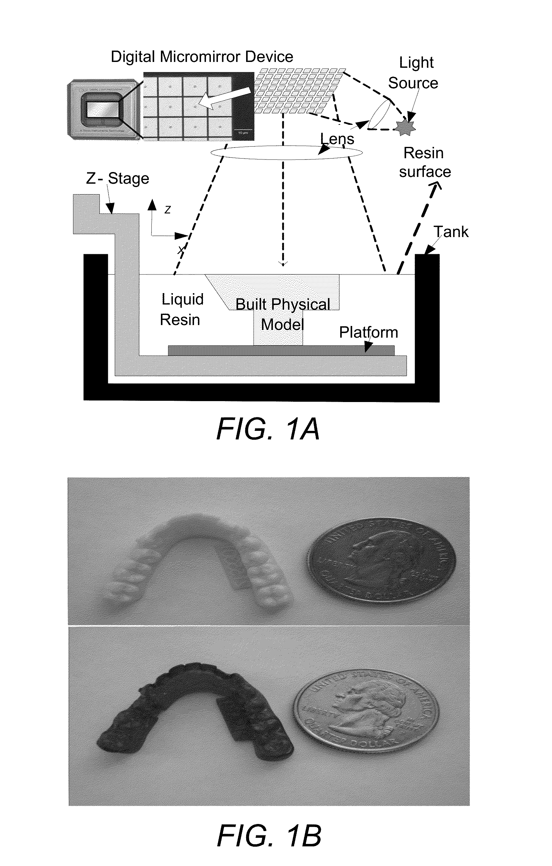
Shearing-Based Recoating Method for the Bottom-Up Projection Based MIP-SL Process

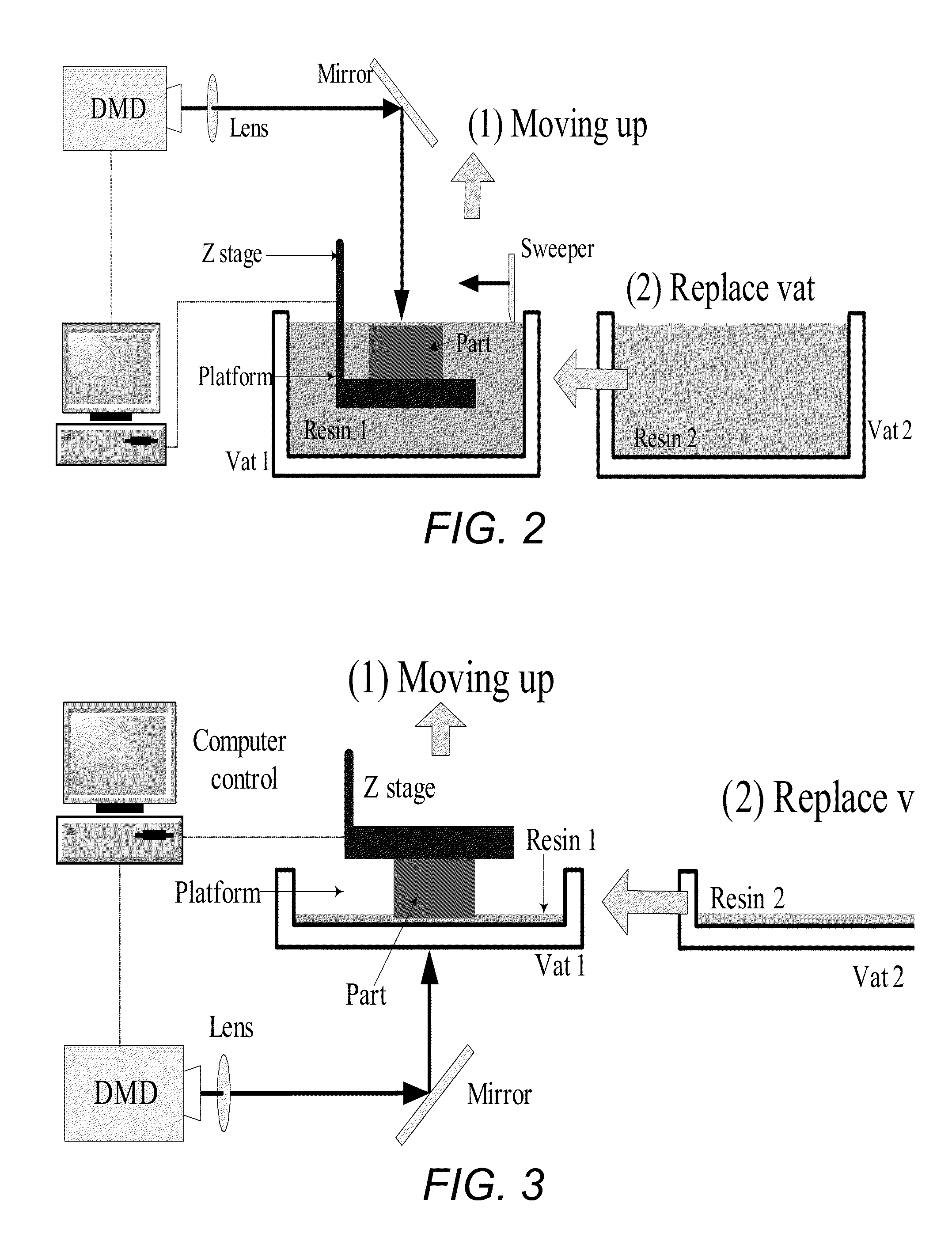
Two-Channel Design for Effective Multi-Material Fabrication

[0076]Building functional microstructures, especially digital material fabrication, may require the development of a general MIP-SL process that can fabricate all combinations of multiple resins. A challenge that may be addressed in such a multi-material MIP-SL system may be reduction of material waste and increase in cleaning efficiency during the resin tank switching process. To address the problem, the bottom-up projection in the multi-material MIP-SL process has been investigated. An illustration o...


PUM

PropertyMeasurementUnit
thicknessaaaaaaaaaa
thicknessaaaaaaaaaa
thicknessaaaaaaaaaa

Abstract

A three-dimensional object may be produced in cascaded layers from a liquid resin that solidifies upon exposure to light. A translation stage may be positioned relative to a vat that is suitable for solidifying the highest un-solidified layer of the three-dimensional object directly beneath any existing, solidified layers of the three-dimensional object. A mask image projection system may project a two-dimensional image of the highest un-solidified layer through a transparent bottom of the vat and into the liquid resin. This may cause at least a portion of the liquid resin to solidify in the shape of the two-dimensional image and to adhere to the bottom of a surface beneath the solidified layer. A shearing force may be applied between the bottom surface of the solidified layer and the surface beneath that is great enough to detach the solidified layer from the surface beneath.

Description

CROSS-REFERENCE TO RELATED APPLICATIONS[0001]This application is based upon and claims priority to U.S. provisional patent application 61 / 639,570, entitled “DIGITAL MASK-IMAGE-PROJECTION-BASED ADDITIVE MANUFACTURING FOR THE FABRICATION OF DIGITAL MATERIALS,” filed Apr. 27, 2012, attorney docket number 028080-0735, and U.S. provisional patent application 61 / 650,876, entitled “A FAST MASK PROJECTION STEREOLITHOGRAPHY PROCESS FOR BUILDING DIGITAL MODELS IN MINUTES,” filed May 23, 2012, attorney docket number 028080-0748.BACKGROUND[0002]1. Technical Field[0003]This disclosure relates to digital mask-image-projection-based additive manufacturing.[0004]2. Description of Related Art[0005]Layer-based additive manufacturing (AM) manufactures solid objects by the sequential delivery of energy and / or material to specified points in space to produce those solid objects. Multiple materials or functionally graded material may be added in a single component during the building process. An example ...

Claims


Application Information

Patent Timeline
Patent Type & Authority Applications(United States)
IPC IPC(8): B29C67/00
CPCB29C67/0088B29C67/007B29C67/00B29C64/129B33Y30/00B33Y10/00B33Y50/02
Inventor CHEN, YONGZHOU, CHI
Owner UNIV OF SOUTHERN CALIFORNIA
Why Eureka
Try Eureka