Distal bearing support

Active Publication Date: 2013-11-14
TC1 LLC
View PDF3 Cites 143 Cited by
  • Summary
  • Abstract
  • Description
  • Claims
  • Application Information

AI Technical Summary

Problems solved by technology

Operation of the motor can cause rotation of the impeller to draw blood into the lumen.

Method used


Image

  • Distal bearing support
  • Distal bearing support
  • Distal bearing support

Examples


Embodiment Construction

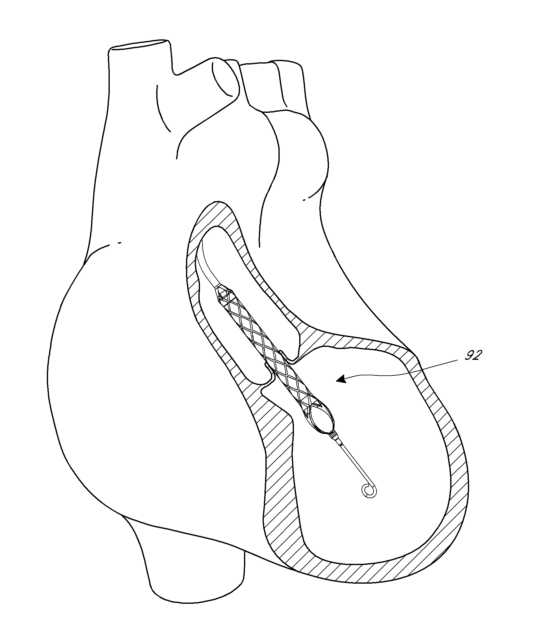
[0024]This application is directed to apparatuses for inducing motion of a fluid relative to the apparatus. In particular, the disclosed embodiments generally relate to various configurations for supporting an impeller disposed at a distal portion of a percutaneous catheter pump. As discussed in greater detail below, such supporting structure can be advantageous to minimize excursion of a high speed impeller toward or into a structure forming an inside surface of a cannula within which the impeller rotates. For example, in the disclosed embodiments, the cannula can be flexible, and the impeller can be flexibly supported off a distal end of the impeller shaft by a support member. In addition, the disclosed supporting structure can be advantageous at high impeller speeds and when the impeller and cannula are subject to hydraulic forces. The disclosed supports can act in various embodiments to maintain separation between the cannula and the impeller under various conditions. This suppo...


PUM


Abstract

In various embodiments, a catheter pump is disclosed herein. The catheter pump can include an elongated catheter body having a distal portion including an expandable cannula having an inlet and an outlet. The expandable cannula can have a delivery profile and an operational profile larger than the delivery profile. An impeller assembly can include an impeller shaft, and an impeller body can include one or more blades. The impeller blades can draw blood into the cannula when rotated. Further, an expandable support can have a mounting portion disposed on the impeller shaft distal of the impeller body and a cannula contact portion for reducing a change in tip gap due to bending of the cannula. The cannula contact portion can be disposed distal of the mounting portion.

Description

INCORPORATION BY REFERENCE TO ANY PRIORITY APPLICATIONS[0001]Any and all applications for which a foreign or domestic priority claim is identified in the Application Data Sheet as filed with the present application, including U.S. Application No. 61 / 646,755 filed May 14, 2012 entitled Distal Bearing Support, are hereby incorporated by reference under 37 CFR §1.57.BACKGROUND OF THE INVENTION[0002]1. Field of the Invention[0003]This application is directed to pumps for mechanical circulatory support of a heart. In particular, this application is directed to support structures for an impeller assembly that can be used in a catheter pump.[0004]2. Description of the Related Art[0005]Heart disease is a major health problem that has high mortality rate. Physicians increasingly use mechanical circulatory support systems for treating heart failure. The treatment of acute heart failure requires a device that can provide support to the patient quickly. Physicians desire treatment options that ...

Claims


Application Information

Patent Timeline
Patent Type & Authority Applications(United States)
IPC IPC(8): A61M1/10A61M60/13A61M60/174A61M60/216A61M60/411A61M60/508A61M60/81A61M60/825A61M60/857
CPCA61M1/10A61M60/824A61M60/414A61M60/411A61M60/857A61M60/81A61M60/508A61M60/13A61M60/825A61M60/237A61M60/174A61M60/216A61M60/148F04D1/00F04D25/06
Inventor KEENAN, RICHARD L.FITZGERALD, KEIF M.
Owner TC1 LLC
Why Eureka
Try Eureka