Automatic stop and restart device for an engine

a technology of automatic stop and restart device, which is applied in the direction of engine starter, electric control, instruments, etc., can solve the problems of mechanism breakage, noise generation or mechanism breakage, and mechanism breakag

Inactive Publication Date: 2013-11-14
MITSUBISHI ELECTRIC CORP
View PDF11 Cites 0 Cited by
  • Summary
  • Abstract
  • Description
  • Claims
  • Application Information

AI Technical Summary

Benefits of technology

[0014]The present invention has been made for solving the above-mentioned problem, and an object thereof is to provide an automatic stop and restart device for an engine that is capable of suppressing occurrence of an abnormal condition such as noise or a breakdown even if an engine restart condition is satisfied in an automatic engine stop process and a transmission state is changed during an engine restart process thereafter.

Problems solved by technology

However, the conventional device as disclosed in Japanese Patent No. 4214401 considers nothing about the case where the driver selects the non-drive range during the engine restart process.
As a result, in the conventional device as disclosed in Japanese Patent No. 4214401, there is a risk that noise is generated or a mechanism is broken.
Therefore, noise may be generated or the mechanism may be broken.

Method used


Image

  • Automatic stop and restart device for an engine
  • Automatic stop and restart device for an engine
  • Automatic stop and restart device for an engine

Examples


embodiment 1

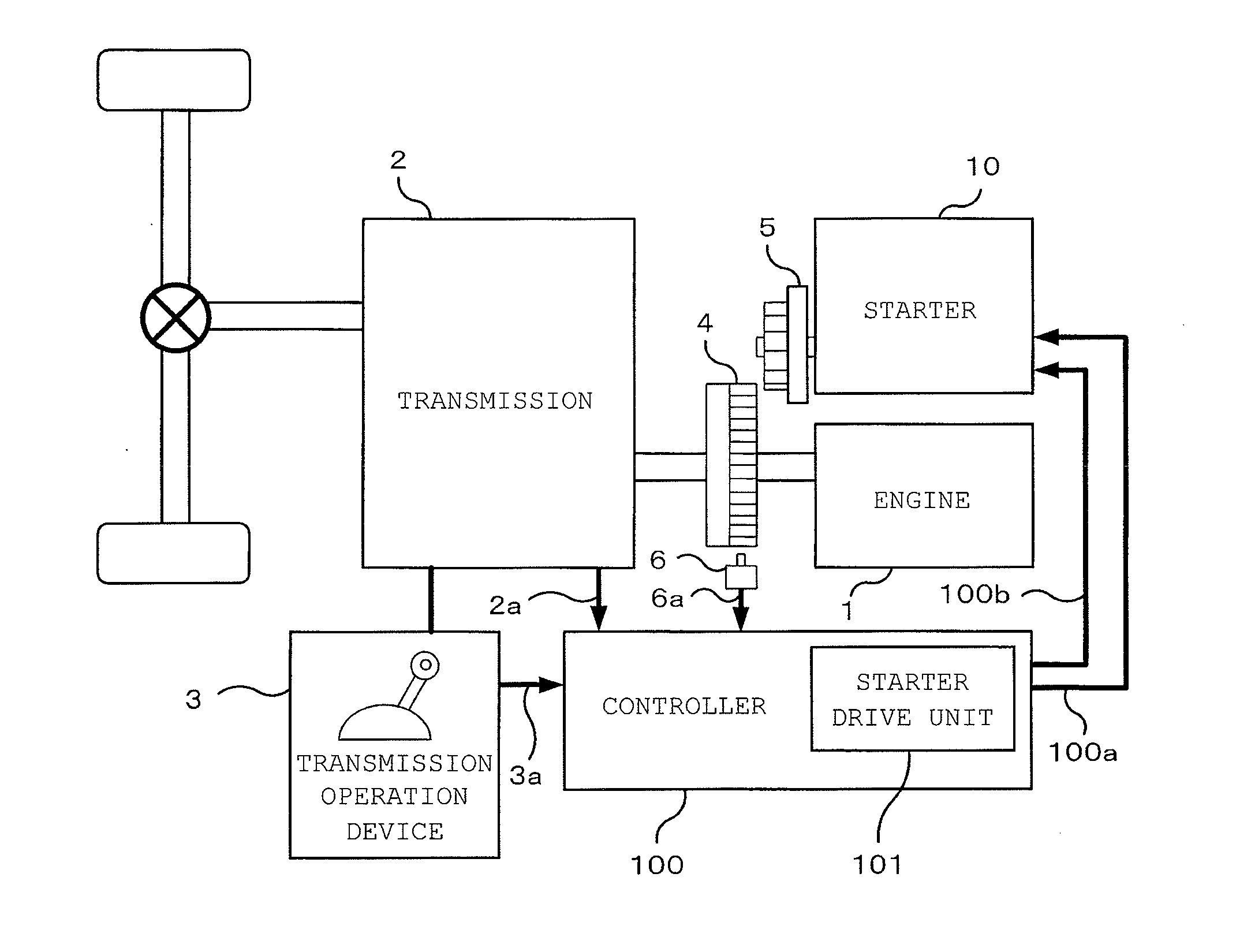
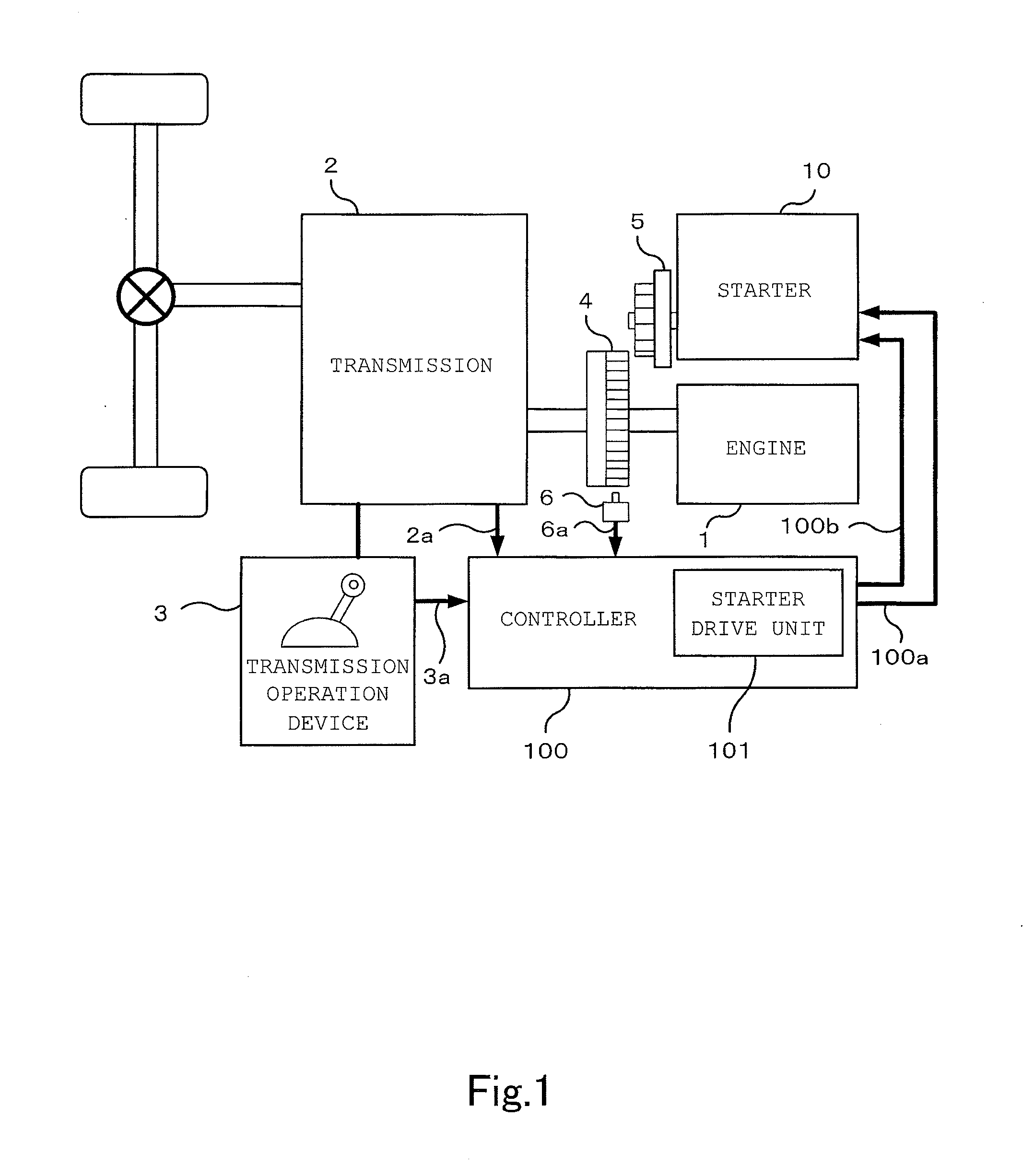
[0051]FIG. 1 is a configuration diagram illustrating an automatic stop and restart device for an engine according to Embodiment 1 of the present invention.

[0052]In FIG. 1, a crank shaft of an engine (internal-combustion engine) 1 to be a source of power for a vehicle is connected to a transmission 2. The transmission 2 changes gears and transmits power of the engine 1 after changing gears. The driveline of the engine 1 is transmitted to driving wheels of the vehicle. The transmission 2 is connected to a transmission operation device 3. The transmission operation device 3 changes a transmission state (gear shift) of the transmission 2 in accordance with driver's transmission operation (lever operation or shift operation).

[0053]In addition, the crank shaft of the engine 1 is provided with a ring gear 4 that rotates together with the crank shaft. Near the ring gear 4, there are disposed a pinion gear 5 that can engage with the ring gear 4 and ring gear rotation speed detection means 6 ...

embodiment 2

[0101]In Embodiment 1, the two types of pinion gear thrust timings are used for the controller 100 to control drive of the pinion gear thrust means 12, and hence occurrence of an abnormal condition such as noise or a breakdown can be suppressed when the transmission state is changed during the engine restart process. In contrast, in Embodiment 2, the controller 100 controls the transmission state of the transmission 2 so as to suppress occurrence of an abnormal condition such as noise or a breakdown when the transmission state is changed during the engine restart process. A configuration of Embodiment 2 is the same as that of Embodiment 1, but the operation timings of the controller 100 are different between Embodiment 1 and Embodiment 2.

[0102]Next, the operation timings of the controller 100 of Embodiment 2 are described. FIG. 12 is a timing chart illustrating the operation timings of the controller 100 in the automatic engine stop and restart process according to Embodiment 2 of t...

embodiment 3

[0118]In Embodiment 1, the two types of pinion gear thrust timings are used for the controller 100 to control drive of the pinion gear thrust means 12, and hence occurrence of an abnormal condition such as noise or a breakdown can be suppressed when the transmission state is changed during the engine restart process. In contrast, in Embodiment 3, in a case where the pinion gear 5 and the ring gear 4 cannot engage with each other, the controller 100 stops the engine restart process so as to suppress occurrence of an abnormal condition such as noise or a breakdown when the transmission state is changed during the engine restart process. A configuration of Embodiment 3 is the same as that of Embodiment 1, but the operation timings of the controller 100 are different between Embodiment 1 and Embodiment 3.

[0119]Next, the operation timings of the controller 100 of Embodiment 3 are described. FIG. 16 is a timing chart illustrating the operation timings of the controller 100 in the automati...


PUM


Abstract

Provided is an automatic stop and restart device for an engine that is capable of suppressing occurrence of an abnormal condition even if a transmission state is changed during an engine restart process after an engine restart condition is satisfied in an automatic engine stop process. A controller performs the automatic engine stop process and the engine restart process. If a determined state of a transmission is a drive range, a transmission state determination unit drives a pinion gear thrust unit at timing determined by a first pinion gear thrust timing determination unit. If the determined state of the transmission is a non-drive range, the transmission state determination unit drives the pinion gear thrust unit at timing determined by a second pinion gear thrust timing determination unit.

Description

CROSS-REFERENCE TO RELATED APPLICATION[0001]This application is a divisional of U.S. application Ser. No. 12 / 957,956 filed Dec. 1, 2010, which is the disclosure of which is incorporated herein by reference in its entirety.BACKGROUND OF THE INVENTION[0002]1. Field of the Invention[0003]The present invention relates to an automatic stop and restart device for an engine, which stops an engine automatically when a predetermined automatic engine stop condition is satisfied and restarts the engine when a predetermined restart condition is satisfied after the automatic engine stop condition is satisfied.[0004]2. Description of the Related Art[0005]In recent years, there are developed automatic engine stop and restart systems which stop an engine automatically and then restart the engine automatically for a purpose of improving fuel efficiency of automobiles or decreasing environmental load. The automatic engine stop and restart system automatically stops the engine if a predetermined autom...

Claims


Application Information

Patent Timeline
Patent Type & Authority Applications(United States)
IPC IPC(8): F02D45/00
CPCF02D45/00F02N11/0844F02N11/0855F02N2200/022F02N2200/048F02N2200/0802F02N2300/2006F02N2300/2011B60W10/115B60W30/18018B60W2510/101B60W2710/1005F02N11/0825Y02T10/40B60W10/06B60W10/10
Inventor HAYASHI, KENSUKEISHIKAWA, OSAMUSHODA, TOMOHISA
Owner MITSUBISHI ELECTRIC CORP
Why Eureka
Try Eureka