Solar module apparatus with edge reflection enhancement and method of making the same

a solar module and edge light reflection technology, applied in the field of solar modules, can solve the problems of reducing the efficiency of solar energy production, so as to achieve enhanced edge light reflection and enhance edge light reflection. effect, the effect of enhancing the efficiency

Inactive Publication Date: 2013-11-21
CM MFG
View PDF12 Cites 17 Cited by
  • Summary
  • Abstract
  • Description
  • Claims
  • Application Information

AI Technical Summary

Benefits of technology

[0008]In yet another specific embodiment, the present invention provides a method for solar module lamination with enhanced edge light reflection. The method includes providing a plurality of photovoltaic cells formed overlying substantially entire surface region of a glass substrate except vicinities of peripheral edge regions. The method further includes sealing the peripheral edge regions with an edge seal material. Additionally, the method includes applying an encapsulation material over the plurality of photovoltaic cells including the edge seal material. Furthermore, the method includes disposing a top glass panel having a substantially same form factor of the glass substrate to bond with the encapsulation material. Moreover, the method includes wrapping around the top glass panel and the glass substrate by a frame structure having multiple angled-surface members disposed within the vicinities of the peripheral edge regions. The multiple angled-surface members are tilted above edge regions of the top glass panel to redirect incoming sunlight at least partially toward the plurality of photovoltaic cells.
[0009]Many benefits can be achieved by applying the embodiments of the present invention. Particularly, a monolithically integrated thin-film solar module is advantageously assembled by a frame structure with multiple angled-surface members for enhancing edge light reflection so that the photovoltaic active regions can be exposed to more sun light and is able to effectively produce solar energy with enhanced efficiency. In certain embodiments, solar modules without frames can be laminated by applying reflection enhanced edge seal material and mask tape within peripheral edge regions to replace commonly used black-colored edge seal and tape. The reflected or scattered light from the peripheral edge regions can be re-directed, at least partially, back to the photovoltaic active regions by surface of top glass panel of the laminated module or interface between the top glass panel and encapsulation material used for bonding the glass panel. In certain other embodiments, when a plurality of frameless solar modules are assembled to form a solar module array in the field, multiple reflection structures can be disposed in the boundary regions to reflect sun light there toward the module surface regions. The reflector structure can be simply clamped to part of the peripheral edge regions of each laminated solar module that is supported by an assembled mounting rack. These and other benefits may be described throughout the present specification and more particularly below.

Problems solved by technology

Unfortunately, the supply of petrochemical fuel is limited and essentially fixed based upon the amount available on the planet Earth.
Additionally, as more people use petroleum products in growing amounts, it is rapidly becoming a scarce resource, which will eventually become depleted over time.
Although solar energy is environmentally clean and has been successful to a point, many limitations remain to be resolved before it becomes widely used throughout the world.
However, crystalline materials are often costly and difficult to make on a large scale.
Additionally, devices made from such crystalline materials often have low energy conversion efficiencies.
Similar limitations exist with the use of thin film technology in making solar cells.
That is, efficiencies for thin-film photovoltaic cells based on various types of absorber materials are often relatively poor.

Method used


Image

  • Solar module apparatus with edge reflection enhancement and method of making the same
  • Solar module apparatus with edge reflection enhancement and method of making the same
  • Solar module apparatus with edge reflection enhancement and method of making the same

Examples


Embodiment Construction

[0019]The present invention relates generally to techniques for the manufacture of photovoltaic devices. More particularly, the present invention provides a solar module with light reflection enhancement around peripheral edge regions and a method of making the same. Merely by way of examples, the present method is applied to integrate solar modules or solar module array with edge reflection-enhancement, but it would be recognized that the invention may have other applications.

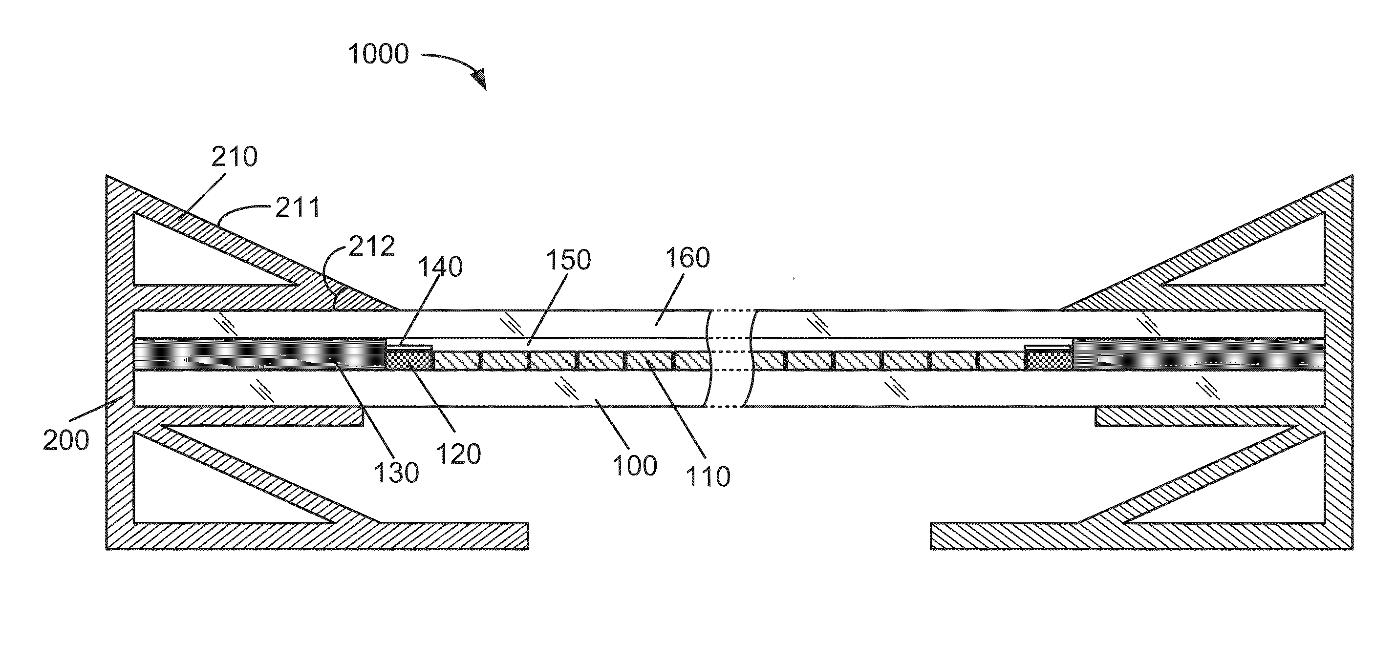
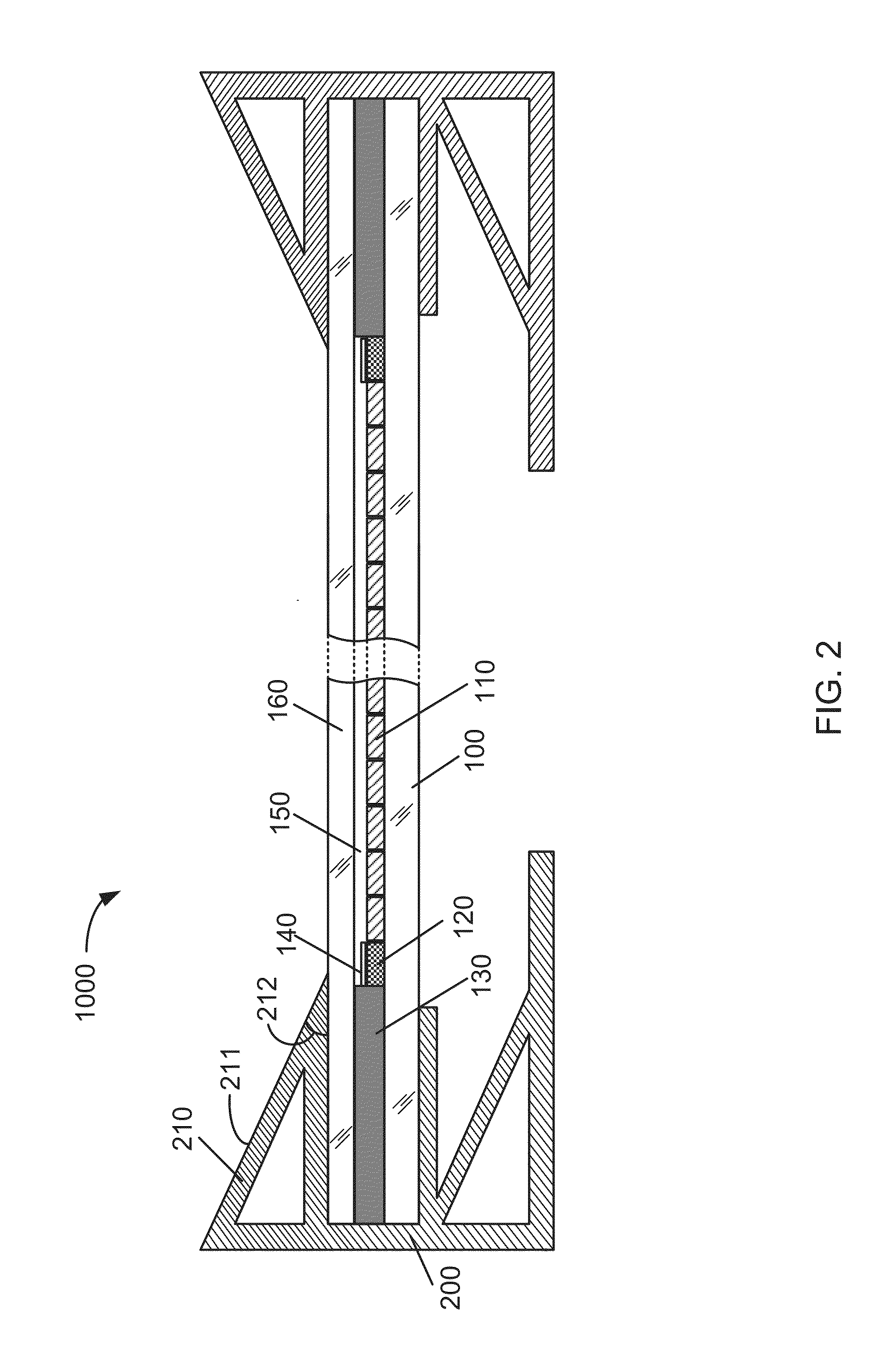
[0020]FIG. 2 is a simplified cross sectional diagram of a framed solar module with edge reflection enhancement according to an embodiment of the present invention. This diagram is merely an example, which should not unduly limit the scope of the claims herein. As shown, the framed solar module 1000 is monolithically integrated based on thin-film photovoltaic active material that formed on a glass substrate 100. In an example, the glass substrate 100 can have various sizes ranging from 6 inch square, 12 inch sq...


PUM


Abstract

A monolithic integrated solar module with edge reflection enhancement includes a plurality of thin-film photovoltaic cells formed overlying a surface region of a glass substrate except in vicinities of peripheral edge regions. The solar module further includes a mask tape applied on a conductor bar disposed within the peripheral edge regions and coupled with the plurality of thin-film photovoltaic cells and an edge seal material disposed within the peripheral edge regions in a vicinity of the mask tape and an end region of the glass substrate. Additionally, the solar module includes a top glass panel disposed overlying the plurality of thin-film photovoltaic cells, the mask tape, and the edge seal material. Moreover, the solar module includes a reflector structure comprising one or more angled surfaces being configured to facilitate scattering of incoming sunlight from the vicinities of the peripheral edge regions partially to the plurality of thin-film photovoltaic cells.

Description

BACKGROUND OF THE INVENTION[0001]The present invention relates generally to techniques for the manufacture of photovoltaic devices. More particularly, the present invention provides a solar module with light reflection enhancement around peripheral edge regions and a method of making the same. Merely by way of examples, the present method is applied to integrate one or more solar modules with both external reflectors and internal reflection-enhanced edge seal materials, but it would be recognized that the invention may have other applications.[0002]From the beginning of time, mankind has been challenged to find way of harnessing energy. Energy comes in the forms such as petrochemical, hydroelectric, nuclear, wind, biomass, solar, and more primitive forms such as wood and coal. Over the past century, modern civilization has relied upon petrochemical energy as an important energy source. Petrochemical energy includes gas and oil. Gas includes lighter forms such as butane and propane, ...

Claims


Application Information

Patent Timeline
Patent Type & Authority Applications(United States)
IPC IPC(8): H01L31/052H01L31/0232
CPCH01L31/0525H01L31/02325Y02E10/52H01L31/0488H02S20/00H02S30/10H02S40/22H02S20/10
Inventor REICHSTETTER, KARLBROWN, ALBERT S.
Owner CM MFG
Why Eureka
Try Eureka