Solar cell

a solar cell and cell technology, applied in the field of solar cells, can solve the problems of degrading reliability against moisture penetration and limit the adhesive force between the upper and lower substrates, and achieve the effect of improving the adhesive force and improving the reliability against moisture penetration

Inactive Publication Date: 2013-11-21
LG INNOTEK CO LTD
View PDF1 Cites 0 Cited by
  • Summary
  • Abstract
  • Description
  • Claims
  • Application Information

AI Technical Summary

Benefits of technology

[0007]According to the solar cell of the embodiment, various patterns are formed between the upper and lower substrates so that a contact area to an adhesive member, which is provided between the upper and lower substrates, is increased, thereby improving adhesive force between the upper and lower substrates.
[0008]In addition, according to the solar cell of the embodiment, the shape of the pattern can be variously modified to lengthen the moisture penetration path so that the reliability against moisture penetration can be improved.

Problems solved by technology

However, since only one adhesive member is provided between the upper substrate and the lower substrate, there is limitation in adhesive force between the upper and lower substrates and the reliability against moisture penetration is degraded.

Method used


Image

  • Solar cell
  • Solar cell
  • Solar cell

Examples


Embodiment Construction

[0014]In the description of the embodiments, it will be understood that when each panel, wire, cell, device, surface, or pattern is referred to as being “on” or “under” another panel, wire, cell, device, surface, or pattern, it can be “directly” or “indirectly” on the other lens, unit, part, hole, protrusion, groove or layer or one or more intervening layers may also be present. Such a position of elements will be explained with reference to the drawings. The thickness and size of each layer shown in the drawings may be exaggerated, omitted or schematically drawn for the purpose of convenience or clarity. In addition, the size of elements does not utterly reflect an actual size.

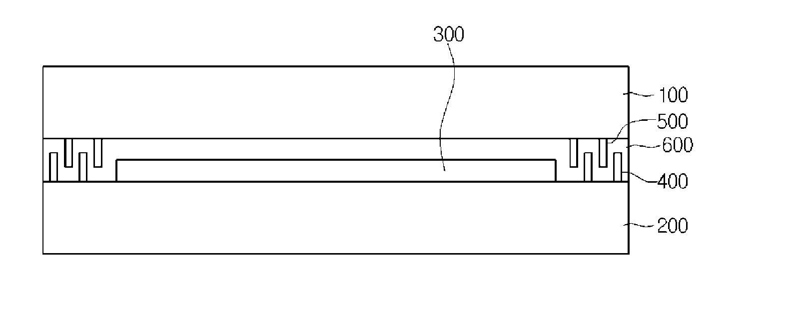
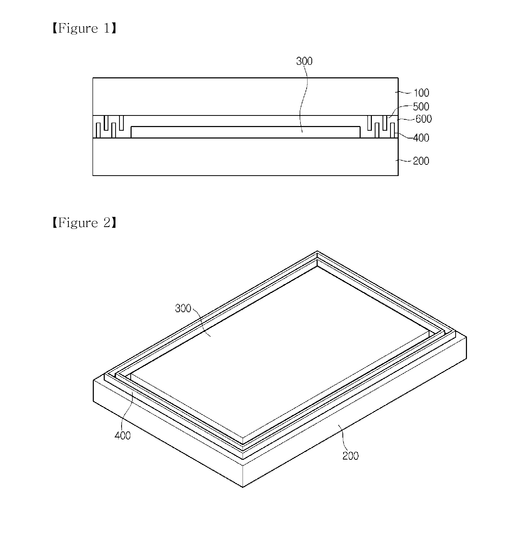
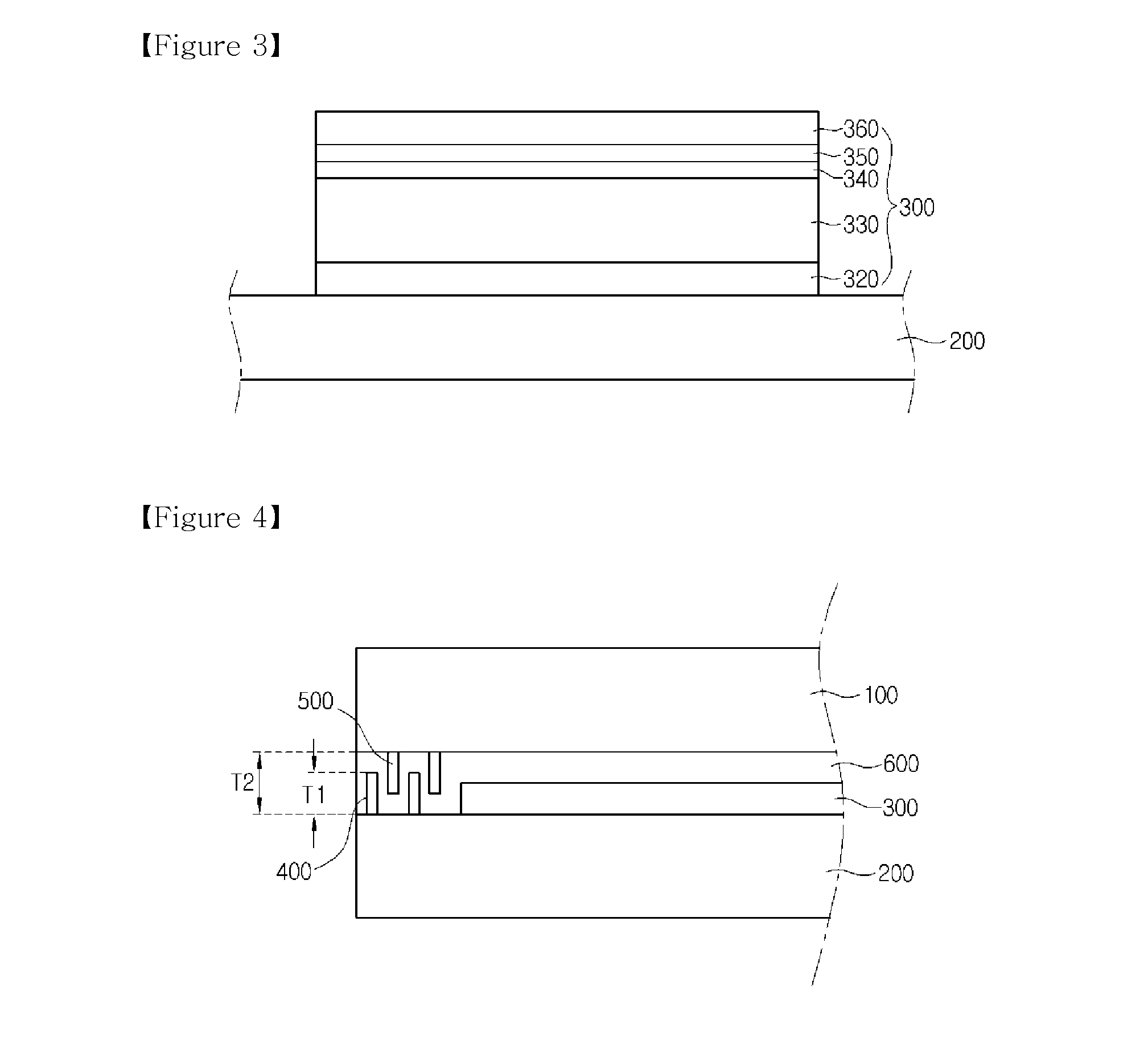
[0015]FIG. 1 is a sectional view showing a solar cell according to the embodiment, FIG. 2 is a perspective view showing a lower substrate having a pattern according to the embodiment, FIG. 3 is a sectional view showing a semiconductor layer formed on a substrate according to the embodiment, FIG. 4 is a partia...


PUM


Abstract

Disclosed is a solar cell including upper and lower substrates facing each other, a semiconductor layer on a predetermined region of the lower substrate, and a pattern protruding from at least one of the upper and lower substrates. Various patterns are formed between the upper and lower substrates so that a contact area to an adhesive member, which is provided between the upper and lower substrates, is increased, thereby improving adhesive force between the upper and lower substrates.

Description

TECHNICAL FIELD [0001]The embodiment relates to a solar cell.BACKGROUND ART [0002]In general, a solar cell converts solar energy into electrical energy. The solar cell has been extensively used for the commercial purpose as energy consumption is increased recently.[0003]According to the related art, the solar cell is fabricated by sequentially laminating a back electrode layer, a light absorbing layer, a transparent electrode layer and an upper substrate on a lower substrate in which the upper substrate horizontally adheres to the uppermost end of the solar cell.[0004]However, since only one adhesive member is provided between the upper substrate and the lower substrate, there is limitation in adhesive force between the upper and lower substrates and the reliability against moisture penetration is degraded.DISCLOSURE Technical Problem [0005]The embodiment provides a solar cell capable of improving an adhesive force between an upper substrate and a lower substrate while enhancing th...

Claims


Application Information

Patent Timeline
Patent Type & Authority Applications(United States)
IPC IPC(8): H01L31/02
CPCH01L31/02H01L31/048H01L31/0488H01L31/0749Y02E10/541H01L31/04
Inventor PARK, GI GON
Owner LG INNOTEK CO LTD
Why Eureka
Try Eureka