Bimetal buss bar assembly

a buss bar and battery technology, applied in the field of battery modules, can solve the problem of time-consuming connections, and achieve the effect of low cos

Active Publication Date: 2013-11-21
TYCO ELECTRONICS LOGISTICS AG (CH)
View PDF1 Cites 29 Cited by
  • Summary
  • Abstract
  • Description
  • Claims
  • Application Information

AI Technical Summary

Benefits of technology

[0005]A need remains for battery modul

Problems solved by technology

Such connections are time consuming, and may have other p

Method used


Image

  • Bimetal buss bar assembly
  • Bimetal buss bar assembly
  • Bimetal buss bar assembly

Examples


Embodiment Construction

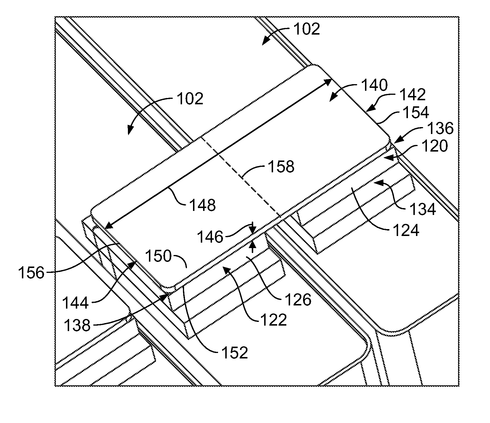
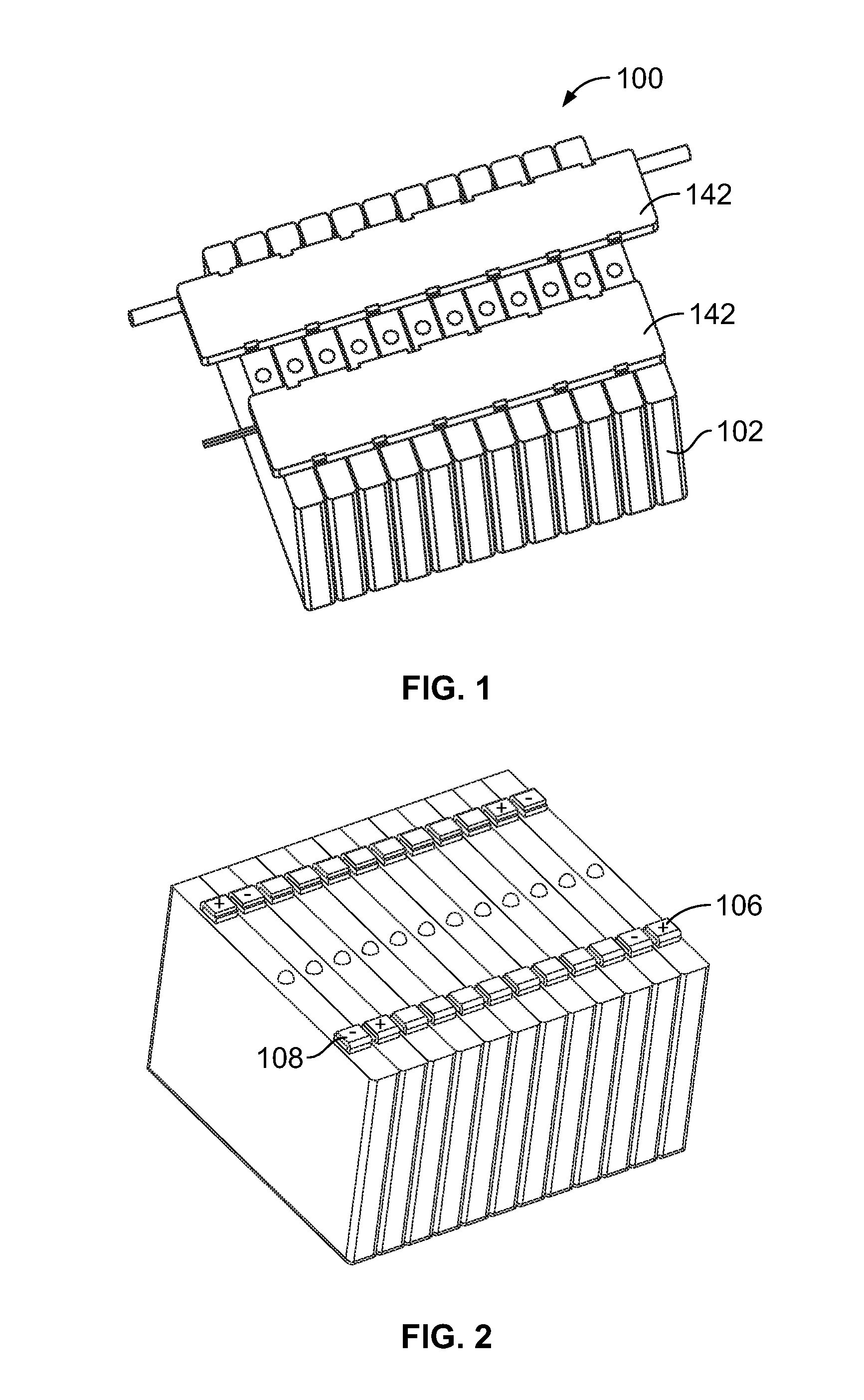
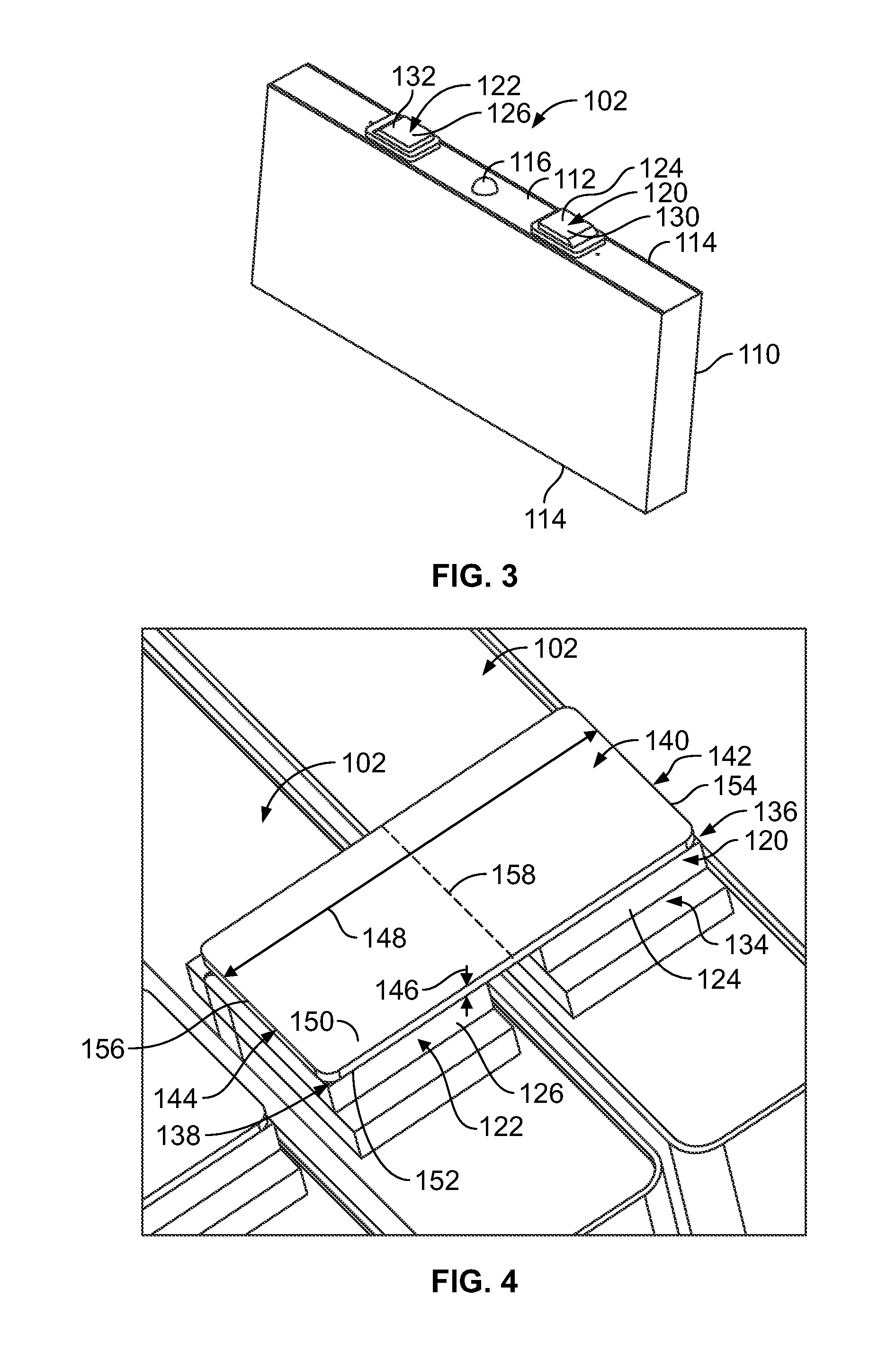
[0031]FIG. 1 is a top perspective view of a battery module 100 formed in accordance with an exemplary embodiment. FIG. 2 is a top perspective view of the battery module 100 with buss bar assemblies 134 (shown in FIG. 4) and a carrier 142 (shown in FIG. 1) for the buss bars 140 removed to illustrate battery cells 102 of the battery module 100. The battery module 100 may be used as part of a battery system in a vehicle, such as an electric vehicle or a hybrid electrical vehicle. The battery module 100 may be used in other applications in alternative embodiments. Multiple battery modules 100 may be ganged together to form a battery pack.

[0032]Each battery module 100 includes a plurality of prismatic battery cells 102. The prismatic battery cells 102 are arranged in a stacked configuration, side-by-side, to form the battery module 100. Optional, the battery module 100 may include a case or other housing that holds the prismatic battery cells 102. A battery cover may be provided over the...


PUM


Abstract

A bimetal buss bar assembly includes a positive battery cell terminal having a flat pad, a negative battery cell terminal having a flat pad, and a buss bar having a negative end and a positive end. The buss bar is attached to the positive battery cell terminal at the positive end and attached to the negative battery cell terminal at the negative end. At least one of the positive battery cell terminal, negative battery cell terminal, and buss bar have a bimetal interface.

Description

CROSS REFERENCE TO RELATED APPLICATIONS[0001]This application claims the benefit of U.S. Provisional Application No. 61 / 735,310 filed Dec. 10, 2012, titled BIMETAL BUSSBAR ASSEMBLY, U.S. Provisional Application No. 61 / 734,674 filed Dec. 7, 2012, titled BIMETAL BUSSBAR ASSEMBLY, and U.S. Provisional Application No. 61 / 649,820 filed May 21, 2012, titled BOLTLESS BATTERY CELL CONNECTION, the subject matter of which are herein incorporated by reference in its entirety.BACKGROUND OF THE INVENTION[0002]The subject matter herein relates generally to battery modules.[0003]Battery modules, such as those for electric vehicles or hybrid vehicles, typically includes a plurality of cells grouped together to form the battery modules. The battery modules are connected together to form battery packs. Each of the cells includes positive and negative cell terminals that are electrically connected together. Different types of battery modules are formed using different types of cells. For example, one ...

Claims


Application Information

Patent Timeline
IPC IPC(8): H01M2/20H01M50/50H01M50/503H01M50/522H01M50/526H01M50/55H01M50/553H01M50/562H01M50/566
CPCH01M2/202H01M2220/20H01M50/553H01M50/55H01M50/503H01M50/566H01M50/522H01M50/50H01M50/562H01M50/526Y02E60/10H01M50/531
Inventor ZHAO, WEIPING
Owner TYCO ELECTRONICS LOGISTICS AG (CH)
Why Eureka
Try Eureka