X-ray detector

a detector and x-ray technology, applied in the field of x-ray detectors, can solve the problems of reducing the expected lifetime of the electronic components involved, affecting the position of electronic components on the rear side in an undesired manner, etc., and achieves the effect of small installation space requirement, easy operation, and easy access to individual components

Inactive Publication Date: 2013-11-21
SIEMENS HEALTHCARE GMBH
View PDF15 Cites 12 Cited by
  • Summary
  • Abstract
  • Description
  • Claims
  • Application Information

AI Technical Summary

Benefits of technology

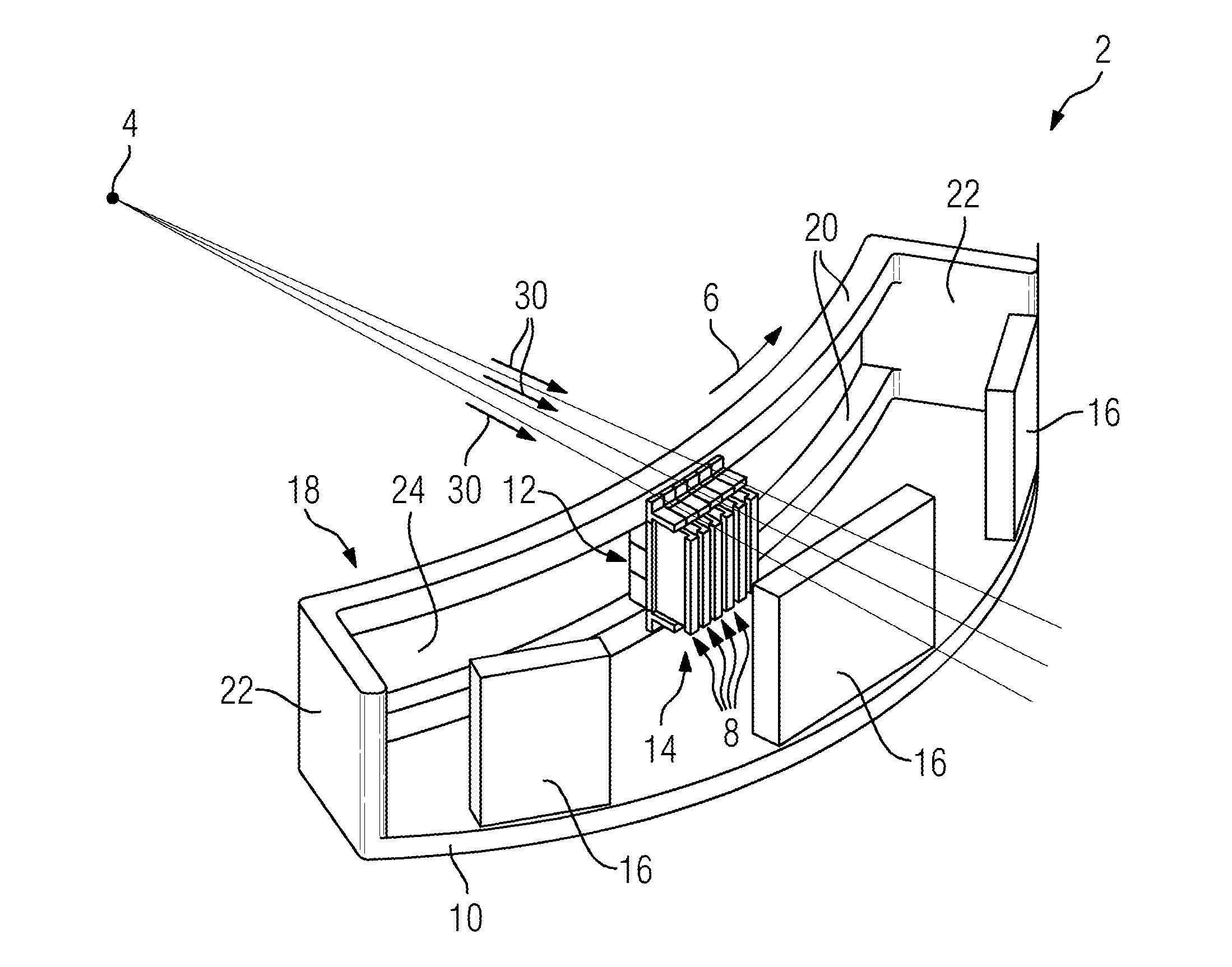
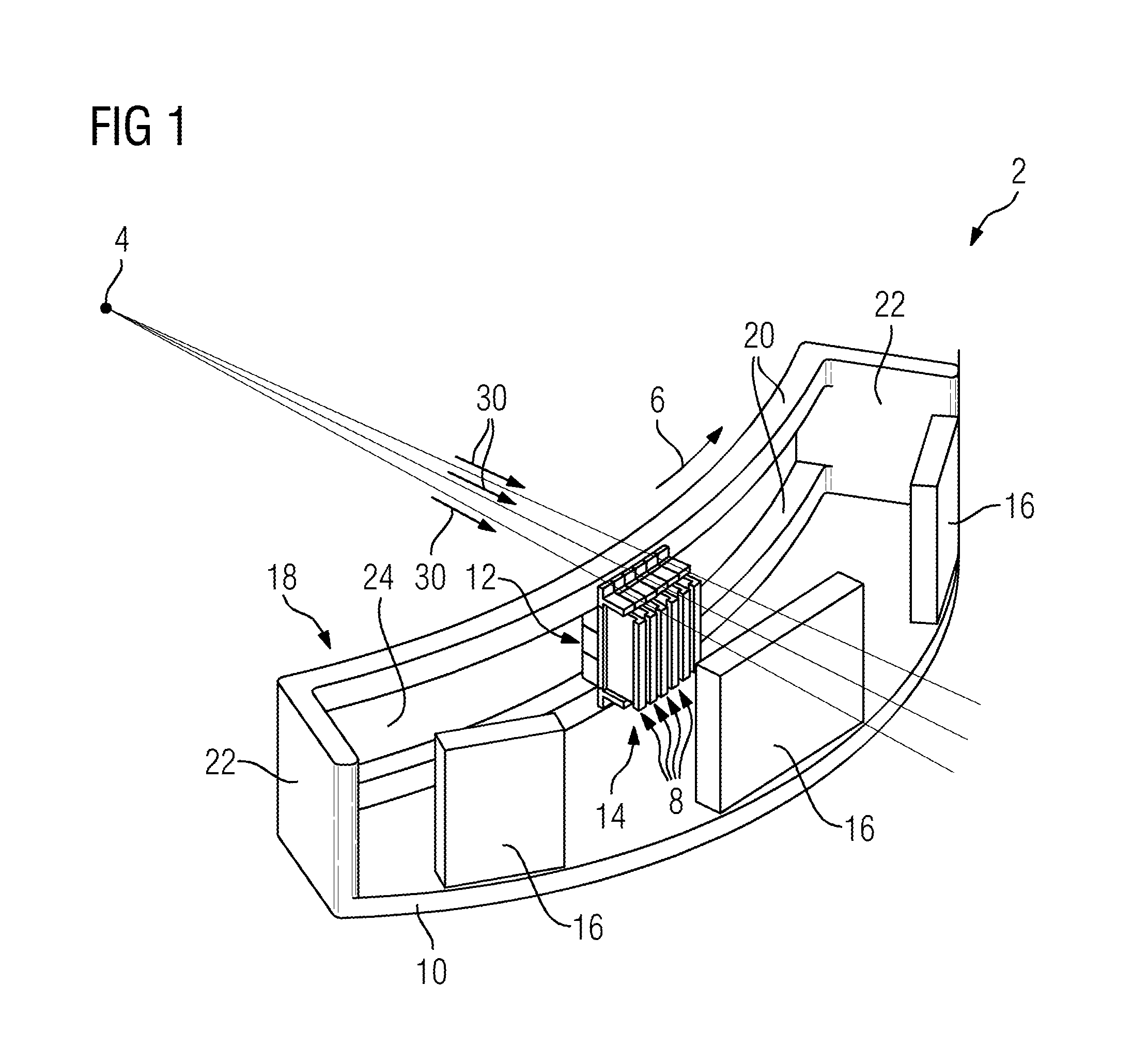
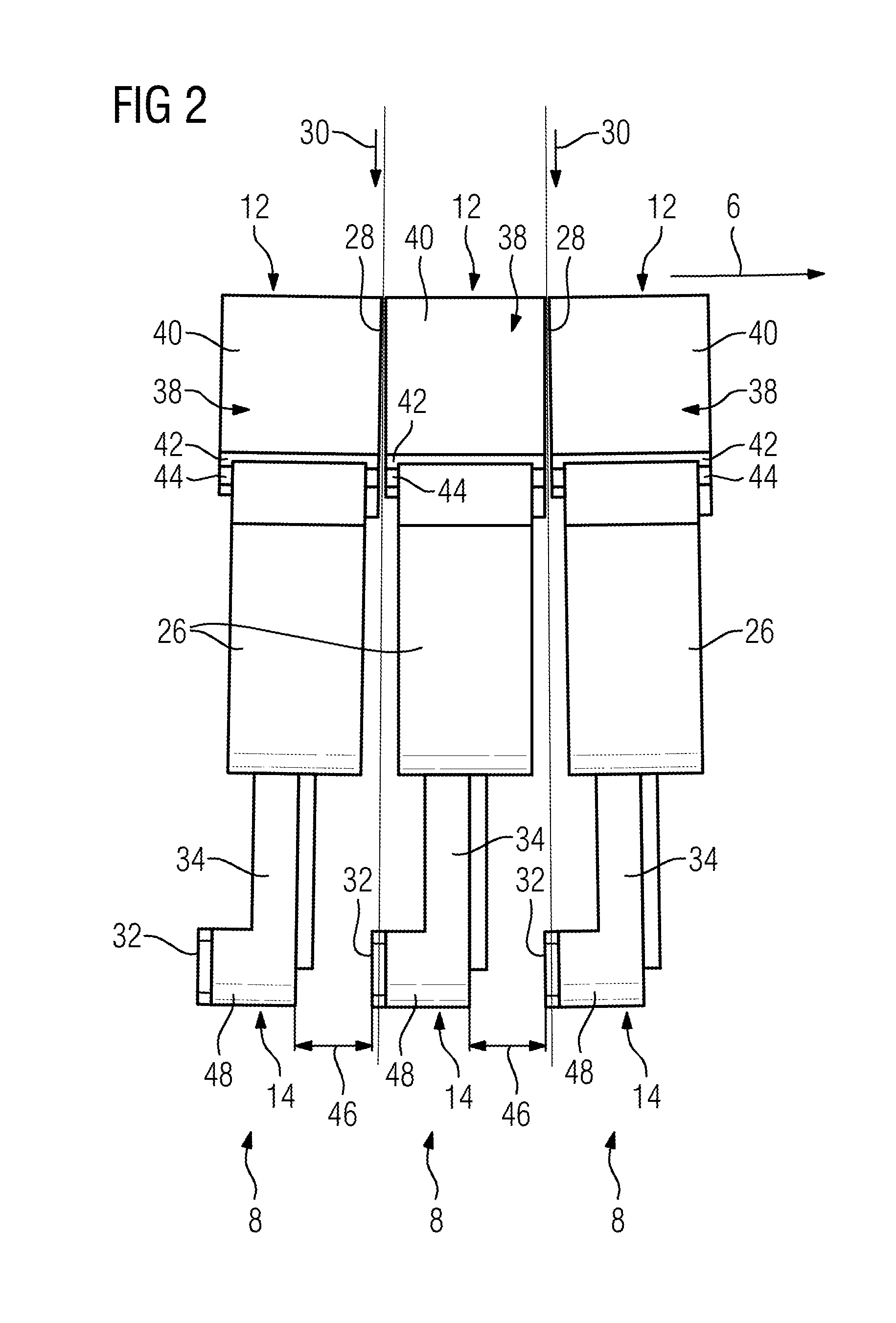
[0010]In accordance with an example embodiment of the x-ray detector, each detector module has a chassis and at least the detector module to which the absorption element is attached comprises a carrier element which connects the absorption element to the chassis, wherein the carrier element is in particular embodied for positioning the absorption element in the stacking direction, i.e. for positioning the absorption element relative to the installation gap. The chassis and the carrier element in such cases are preferably provided by a one-piece, L-shaped profile strip, so that through this on the one hand the absorption element is favorably positioned in the installation state of the x-ray detector and on the other hand through the chassis and also the carrier element, the least possible space is occupied on the rear side. This is of advantage in two respects. On the one hand it allows the x-ray detector to be a more compact design if the individual components from which the x-ray detector is constructed have a comparatively small installation space requirement and on the other hand the components, especially with a given availability of installation space, can be positioned more favorably to the extent that a replacement of individual components in the event of a defect is easier to undertake, since access to the individual components is then especially easy if free space is provided between the individual components.

Problems solved by technology

The x-rays passing through this area are not just lost for recording measurements however, they also influence electronic components positioned on the rear side in an undesired manner.
This especially reduces the expected lifetime of the electronic components involved.

Method used


Image

  • X-ray detector
  • X-ray detector
  • X-ray detector

Examples


Embodiment Construction

[0016]The present invention will be further described in detail in conjunction with the accompanying drawings and embodiments. It should be understood that the particular embodiments described herein are only used to illustrate the present invention but not to limit the present invention.

[0017]Accordingly, while example embodiments of the invention are capable of various modifications and alternative forms, embodiments thereof are shown by way of example in the drawings and will herein be described in detail. It should be understood, however, that there is no intent to limit example embodiments of the present invention to the particular forms disclosed. On the contrary, example embodiments are to cover all modifications, equivalents, and alternatives falling within the scope of the invention. Like numbers refer to like elements throughout the description of the figures.

[0018]Specific structural and functional details disclosed herein are merely representative for purposes of describ...


PUM


Abstract

An x-ray detector, especially for a computed tomograph, includes a number of detector modules arranged next to one another in a stacking direction with a front side, which during operation is oriented towards an x-ray source, and with a rear side lying opposite the front side. For screening against x-rays which pass during operation through an installation between two adjacent detector modules, an absorption element is positioned on the rear side of the two adjacent detector modules.

Description

PRIORITY STATEMENT[0001]The present application hereby claims priority under 35 U.S.C. §119 to German patent application number DE 102012213814.5 filed Aug. 3, 2012, the entire contents of which are hereby incorporated herein by reference.FIELD[0002]At least one embodiment of the invention generally relates to an x-ray detector, especially for a computed tomograph, comprising a number of detector modules disposed next to one another in a stacking direction with a front side which is aligned during operation towards an x-ray radiation source, and with a rear side on the opposite side to the front side.BACKGROUND[0003]X-ray detectors with a large detector surface for recording measurements of x-rays are frequently of modular construction. In such cases individual modules, which are typically of identical construction and each have a number of measuring cells for recording measurements of x-rays, are attached to a module carrier and in this way are disposed in a regular arrangement. In...

Claims


Application Information

Patent Timeline
Patent Type & Authority Applications(United States)
IPC IPC(8): G01T7/00
CPCG01T7/00G01T1/2985
Inventor POHAN, CLAUS
Owner SIEMENS HEALTHCARE GMBH
Why Eureka
Try Eureka