

Side-rolling resistance torsion bar device without fixing supporting seat and rail vehicle
An anti-rolling torsion bar without fixing technology, applied in the field of rail vehicles, can solve problems such as restrictions and large installation space requirements, achieve the effect of small space, reduce installation space requirements, and increase design freedom
- Summary
- Abstract
- Description
- Claims
- Application Information
AI Technical Summary
Problems solved by technology
Method used
Image

Examples
Embodiment 1
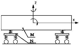
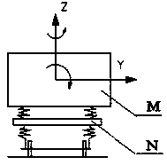
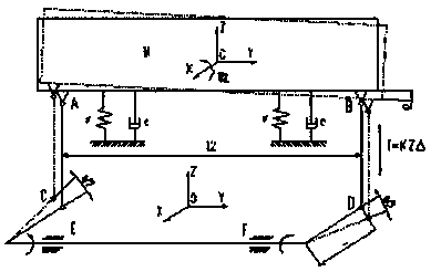
[0037] Example 1, such as Figures 6 to 9 Shown: an anti-rolling torsion bar device without a fixed support seat, including: a torsion bar assembly 1 and two sets of connecting rod assemblies 2, the torsion bar assembly 1 includes: a torsion bar 11 and two torsion arms 12, the The torsion bar 11 is a long bar, and the two ends are fixedly connected with the torsion arm 12 to form a U shape. The torsion bar and the torsion arm can adopt cylindrical interference fit, conical interference fit, or spur spline transition fit. , Straight tooth spline interference fit or bevel tooth spline interference fit and other methods of connection. A joint 13 is provided at the end of the torsion arm 12 away from the torsion bar 11 ; the connecting rod assembly 2 is a dumbbell-shaped bar with a joint 2 22 at one end and a joint 1 3 at the other end. An interface three 14 is also provided on the torsion arm 12 close to the end fixedly connected with the torsion bar 11, the joint one 3 of the c...
Embodiment 2
[0041] Example 2, such as Figures 10 to 11 As shown: the first joint is simply supported joint 4 , and the third interface 14 is a Y-shaped bump fixedly connected to the torsion arm 12 , and the Y-shaped bump is provided with a bolt hole for installing the simply supported joint 4 . The simply supported joint has the advantages of simple structure, large bearing capacity and easy installation.
[0042] The simply supported joint 4 is installed in the first interface 13 , and the simply supported joint 4 is installed in the second interface 22 . The simply supported joint 4 has the advantages of simple structure, large bearing capacity and easy installation.
[0043] The simply supported joint 4 is a short shaft, the two ends of the short shaft are flat square heads 41, and the surface of the flat square head 41 is provided with bolt holes 42 for being installed on the car body M or the bogie N; The middle part of the short axis is a cylindrical protrusion 43 .
[0044] The...
PUM
 Abstract
Description
Claims
Application Information