Multi-frequency antenna

a multi-frequency antenna and antenna technology, applied in the field of antennas, can solve the problems of achieve the effects of preventing mutual interference of the antennae structure, superior impedance matching, and miniaturizing the antenna system

Active Publication Date: 2013-11-21
ADVANCED CONNECTEK INC
View PDF7 Cites 5 Cited by
  • Summary
  • Abstract
  • Description
  • Claims
  • Application Information

AI Technical Summary

Benefits of technology

[0007]The multi-frequency antenna according to the present invention simultaneously has a antenna structure of a dual-band antenna and a antenna structure of a single-band antenna, and can prevent from mutual interference of the antennae structure. Moreover, the antenna structures have common elements, thereby miniaturizing the antenna system. Furthermore, such multi-frequency antenna structure can achieve a superior impedance matching by fine-tuning the length, size and volume of a shorted element, and the length, size and shape of antenna elements are also fine-tuned to make the system bandwidth of the antenna have superior impedance matching.

Problems solved by technology

Moreover, the antenna structures have common elements, thereby miniaturizing the antenna system.

Method used


Image

  • Multi-frequency antenna
  • Multi-frequency antenna
  • Multi-frequency antenna

Examples


first embodiment

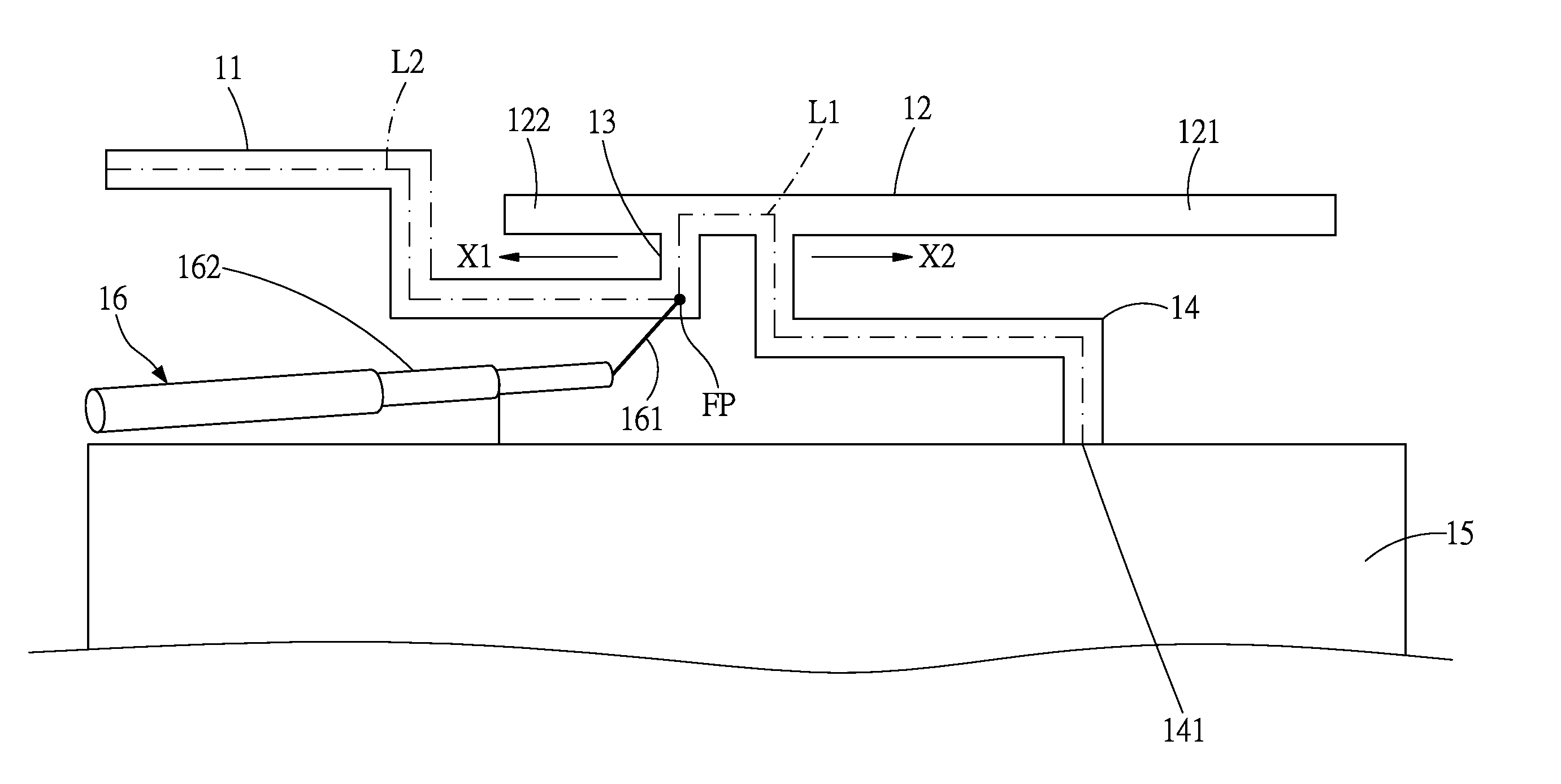
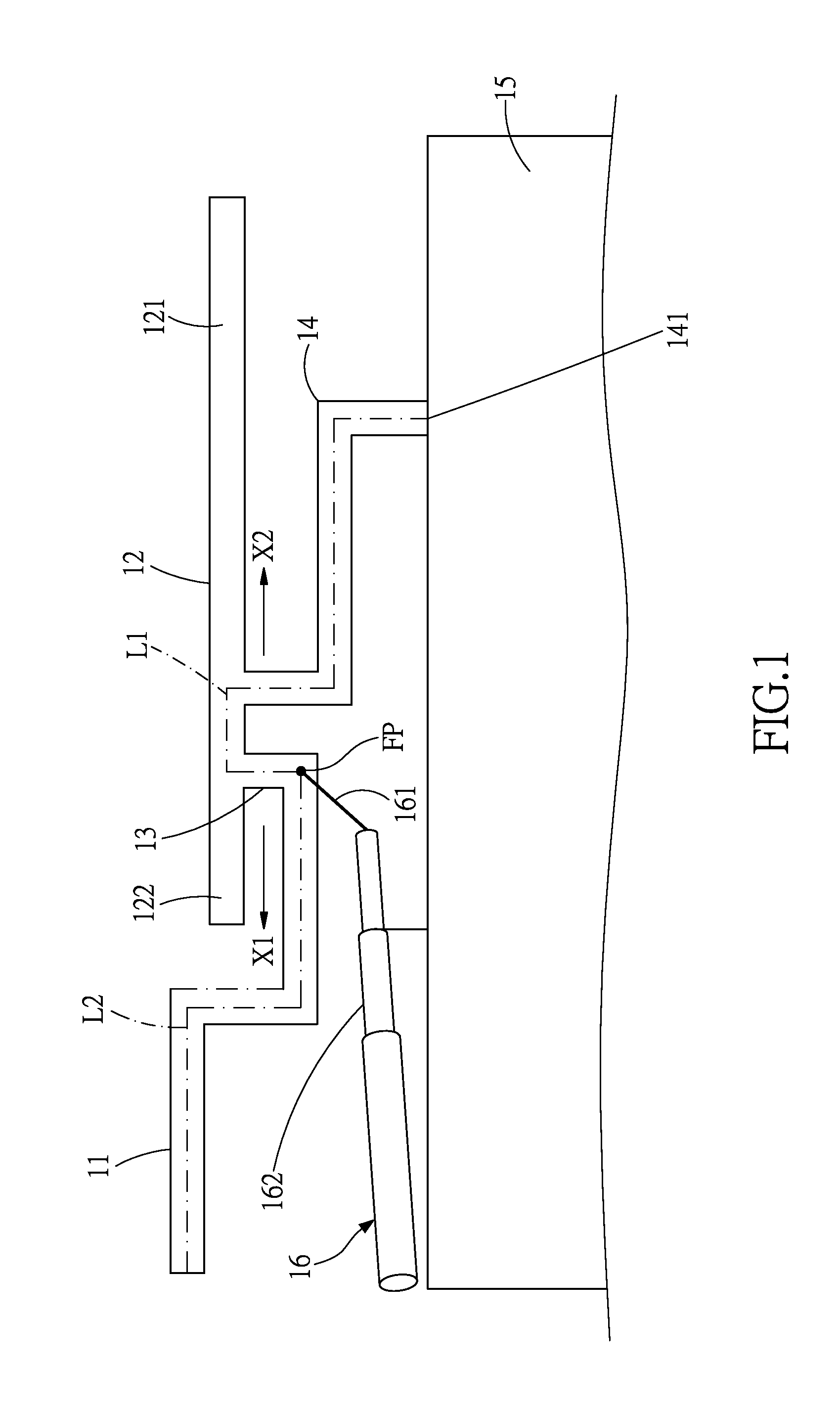
[0016]Refer to FIG. 1, which is a top view of a multi-frequency antenna according to the present invention. The multi-frequency antenna of the present invention comprises a first antenna element 11, a second antenna element 121, a third antenna element 122, a connection element 13, and a shorted element 14. The multi-frequency antenna is disposed on a substrate, which is, for example, a printed circuit board. That is, the first antenna element 11, the second antenna element 121, the third antenna element 122, the connection element 13, and the shorted element 14 are disposed on the substrate.

[0017]The first antenna element 11 defines two ends and has a serpentine shape but the embodiments of the present invention are not limited thereto. One end of the first antenna element 11 is a free end. The other end of the first antenna element 11 is connected to one end of the connection element 13. In other words, the connection element 13 is extended from and perpendicular to the other end ...

second embodiment

[0027]Refer to FIG. 3, which is a diagram showing the measurement results of the voltage standing wave ratio (VSWR) of the multi-frequency antenna according to the present invention, wherein the horizontal axis represents frequency and the vertical axis represents dB. FIG. 3 shows that the operational frequency band S1 ranges from 2.0 to 7.0 GHz, which covers the frequency bands of the WLAN 802.11b / g system (ranging from 2.4 to 2.5 GHz), the WiMAX 2.3G system (ranging from 2.3 to 2.4 GHz), the WiMAX 2.5G (ranging from 2.5 to 2.7 GHz), the WiMAX 3.5G system (ranging from 3.3 to 3.8 GHz), and the WiMAX system (ranging from 4.9 to 2.825 GHz).

[0028]In the standards, an antenna is required to have VSWR lower than 3. Otherwise, the antenna would not have the required performance. FIG. 3 shows that VSWR is lower than 3 in all the frequency bands and lower than 2 in most of the frequency bands. Thus, the operating bandwidth is greatly increased. Therefore, FIG. 3 proves that the operating b...


PUM


Abstract

A multi-frequency antenna includes a first antenna element, a second antenna element, a connection element, a third antenna element and a shorted element. The connection element is connected between the first antenna element and a neighborhood portion of the third antenna element. A feeding point is located in or nearby a first junction between the connection element and the first antenna element or located in the connection element. The shorted element is connected between the second antenna element and the grounding plane. The shorted element extends from a second junction between the second antenna element and the third antenna element to the grounding plane. The first conductive path that extends from the feeding point to the other end of the shorted element is substantially equal to a second conductive length that extends from the feeding point to the free end of the first antenna element.

Description

CROSS-REFERENCES TO RELATED APPLICATIONS[0001]This non-provisional application claims priority under 35 U.S.C. §119(a) on patent application Ser. No. 13 / 025,000 filed in United States. on Feb. 10, 2011, the entire contents of which are hereby incorporated by reference.BACKGROUND OF THE INVENTION[0002]1. Field of the Invention[0003]The present invention relates to an antenna, and more particularly to a multi-frequency antenna, which integrates several operating frequency bands therein.[0004]2. Descriptions of the Related Art[0005]With fast progress of wireless communication technology, RF channels become more and more crowded. Wireless communication technology has expanded from dual-band systems to triple-band or even quad-band systems. In 2007, the industry of notebook computer's antenna has a bigger change: The wireless communication begins to enter the 3G or 3.5G age after the Centrino chip had pushed maturation of built-in WLAN. Thus, the number of the built-in antennae also incr...

Claims


Application Information

Patent Timeline
Patent Type & Authority Applications(United States)
IPC IPC(8): H01Q9/16
CPCH01Q9/16H01Q1/2266H01Q9/26H01Q5/371
Inventor CHIU, TSUNG-WENHSIAO, FU-RENCHANG, YAO-YUANFU, KUO-CHAN
Owner ADVANCED CONNECTEK INC
Why Eureka
Try Eureka