3-dimensional image display device and display method thereof

a display device and 3d image technology, applied in the field of 3d image display devices and display methods of 3d image displays, can solve the problems of preventing the viewer from recognizing a normal 3-dimensional image and the inability to display a 3-dimensional image normally, and achieve the effect of improving the quality of the viewer

Active Publication Date: 2013-11-21
SAMSUNG DISPLAY CO LTD
View PDF6 Cites 35 Cited by
  • Summary
  • Abstract
  • Description
  • Claims
  • Application Information

AI Technical Summary

Benefits of technology

[0031]In one or more exemplary embodiments, the 3-dimensional image display device and the display method thereof which operates based on a predetermined condition as described above provide an image with substantially improved quality to a viewer when the viewer is positioned at a distance greater than or less than an optimum distance or when the number of viewers is greater than or equal to two.

Problems solved by technology

In a conventional autostereoscopic type 3-dimensional image display device, a viewer in a predetermined position relative to a screen may recognize a 3-dimensional image without defect, but when the viewer is not in the predetermined position, cross-talks may occur, that is, a left-eye image may be seen by the right eye of the viewer, which may prevent the viewer from recognizing a normal 3-dimensional image.
In such a conventional autostereoscopic type 3-dimensional image display device, a normal 3-dimensional image may not be normally displayed due to a lens aberration, a pitch error, a gap error and the like which may occur during a manufacturing process.

Method used

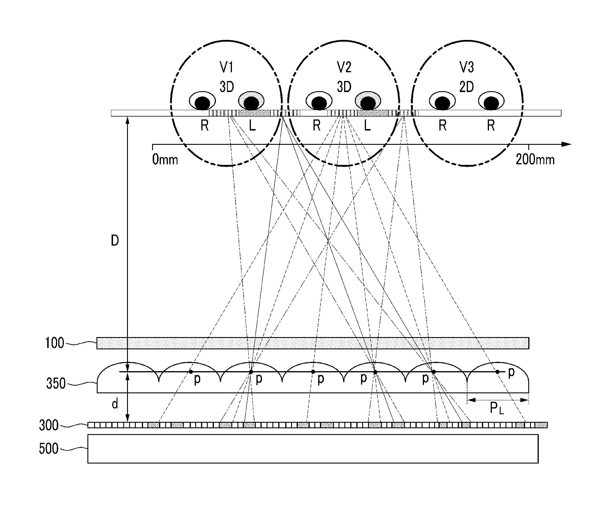
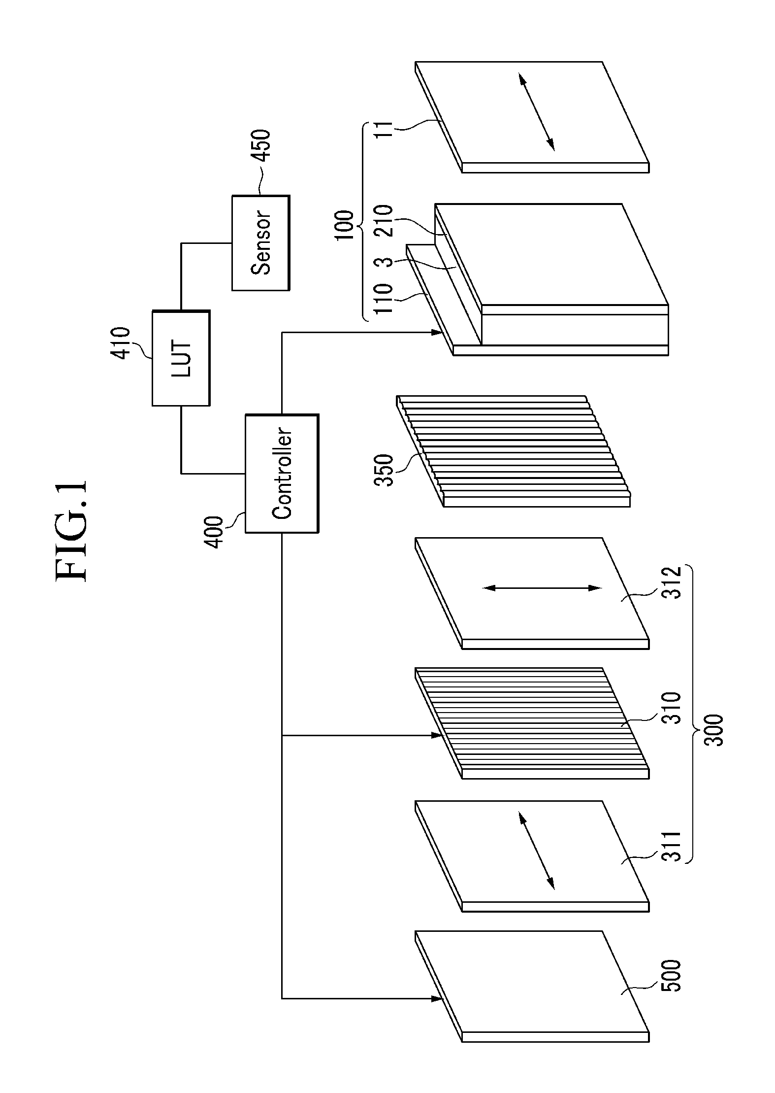
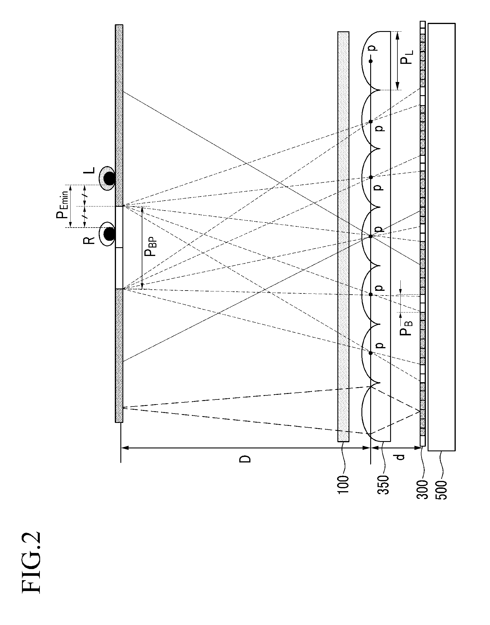

Image

  • 3-dimensional image display device and display method thereof
  • 3-dimensional image display device and display method thereof
  • 3-dimensional image display device and display method thereof

Examples


Embodiment Construction

[0040]The invention will be described more fully hereinafter with reference to the accompanying drawings, in which various embodiments are shown. This invention may, however, be embodied in many different forms, and should not be construed as limited to the embodiments set forth herein. Rather, these embodiments are provided so that this disclosure will be thorough and complete, and will fully convey the scope of the invention to those skilled in the art. Like reference numerals refer to like elements throughout.

[0041]It will be understood that when an element or layer is referred to as being “on”, “connected to” or “coupled to” another element or layer, it can be directly on, connected or coupled to the other element or layer or intervening elements or layers may be present. In contrast, when an element is referred to as being “directly on,”“directly connected to” or “directly coupled to” another element or layer, there are no intervening elements or layers present. Like numbers re...


PUM

PropertyMeasurementUnit
distanceaaaaaaaaaa
speedaaaaaaaaaa
depthaaaaaaaaaa

Abstract

A 3-dimensional image display device includes: a backlight unit; a barrier panel above the backlight unit and including unit barriers which selectively blocks light; a lenticular lens array above the barrier panel and including lenticular lenses, each having a principal point; a liquid crystal panel above the lenticular lens array; an eye tracking sensor which detects a position of eyes of a viewer and a distance between the principal point of the lenticular lenses and the eyes; and a controller which controls the backlight unit, the barrier panel and the liquid crystal panel based on an output of the eye tracking sensor, where the controller turns on and off the unit barriers such that light passes through the principal point of the lenticular lenses to apply a right-eye image to a right eye of the viewer and apply a left-eye image to a left eye of the viewer.

Description

[0001]This application claims priority to Korean Patent Application No. 10-2012-0052163, filed on May 16, 2012, and all the benefits accruing therefrom under 35 U.S.C. §119, the content of which in its entirety is incorporated herein by reference.BACKGROUND[0002](a) Field[0003]Exemplary embodiments of the invention relate to a 3-dimensional image display device and a display method of the 3-dimensional image display device, and more particularly, to an autostereoscopic 3-dimensional image display device and a display method of the autostereoscopic 3-dimensional image display.[0004](b) Description of the Related Art[0005]High-speed information transmission / reception services based on high-speed information and communication networks are recently developed from services, such as current phones, for simply listening and speaking to multimedia services which allows viewers to watch and listen to mainly using digital terminals for processing texts, voices and images at a high speed, and ...

Claims


Application Information

Patent Timeline
Patent Type & Authority Applications(United States)
IPC IPC(8): H04N13/04G02F1/1335
CPCH04N13/0484G02F1/133526H04N13/305H04N13/32H04N13/368H04N13/373H04N13/376H04N2013/403H04N2013/405G02B30/00H04N13/383
Inventor ODAKE, RYOTAOH, SE JOONHAMAGISHI, GORO
Owner SAMSUNG DISPLAY CO LTD
Why Eureka
Try Eureka