Autofocus apparatus

a technology of autofocus and lens, which is applied in the direction of camera focusing arrangement, printers, instruments, etc., can solve the problems of not being able to adapt to taking moving images, and in the in-focus state in which the focus position of the lens corresponds to the object position within the depth of field,

Active Publication Date: 2013-11-21
CANON KK
View PDF3 Cites 11 Cited by
  • Summary
  • Abstract
  • Description
  • Claims
  • Application Information

AI Technical Summary

Benefits of technology

[0008]Therefore, the present invention provides an autofocus apparatus that can always maintain an in-focus state regardless of an object speed or an object distance.
[0010]According to the present invention, it is possible to provide the autofocus apparatus that can always maintain the in-focus state of the object moving in the optical axis direction, regardless of the object speed or the object distance. In addition, it is possible to provide an autofocus apparatus that can always maintain the in-focus state of the object moving in the optical axis direction, regardless of an environmental change or a temporal change of lens characteristics, by relatively adjusting the focus lens drive speed based on an increase or decrease of the defocus amount.

Problems solved by technology

However, the conventional technology disclosed in Japanese Patent Application Laid-Open No. 2001-021794 does not consider individual variation of lens driving performance or a photographing condition which affects lens driving performance because the image pickup lens is driven based on the given function.
In addition, because it is a precondition to take still images, it is not adaptive to taking moving images using a camera or a video camera.
However, in a period between the points of time t1 and t2 during which the exposure point is not reached, the in-focus state in which the focus position of the lens corresponds to the object position within the depth of field cannot be maintained.

Method used


Image

  • Autofocus apparatus
  • Autofocus apparatus
  • Autofocus apparatus

Examples


first embodiment

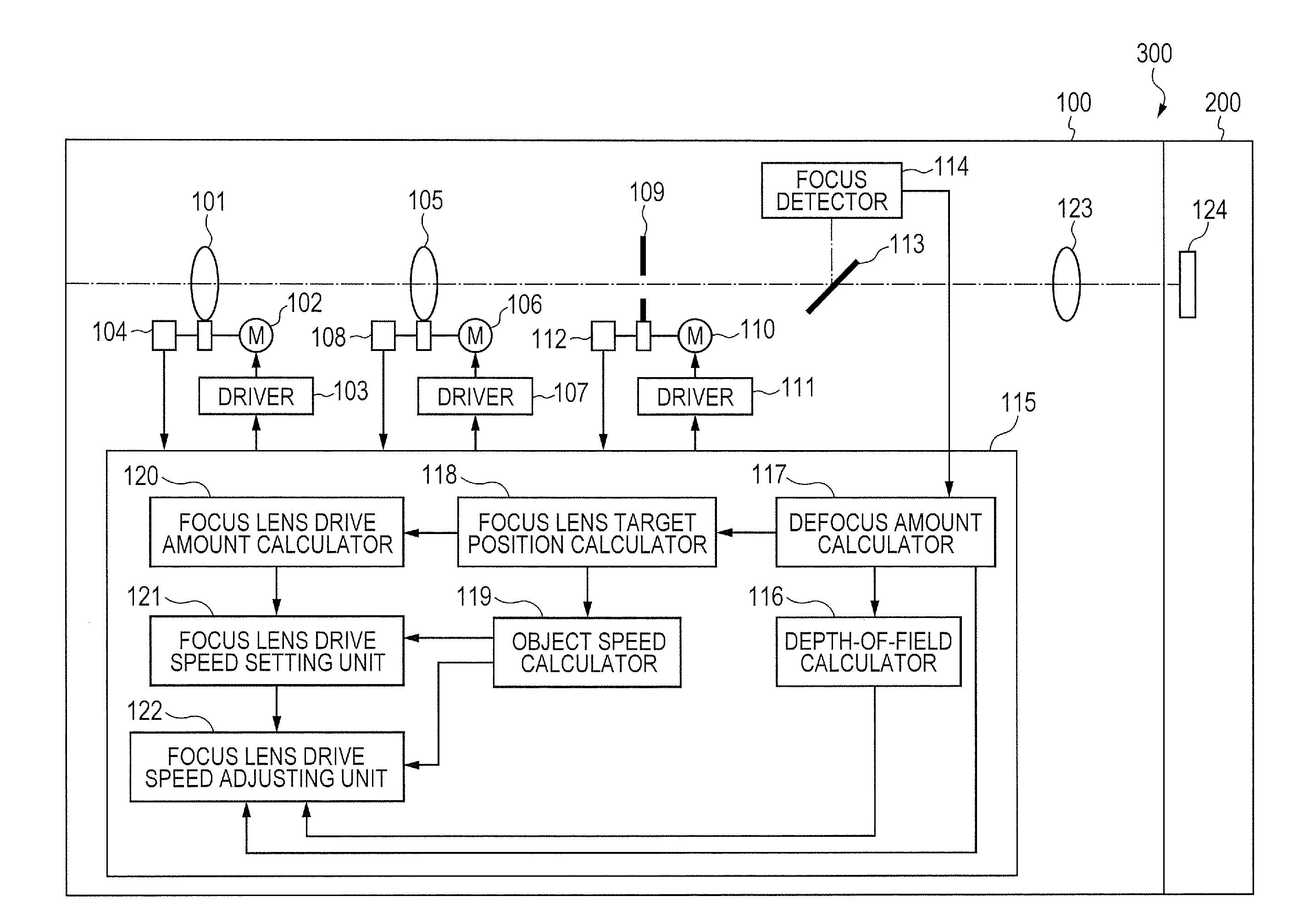
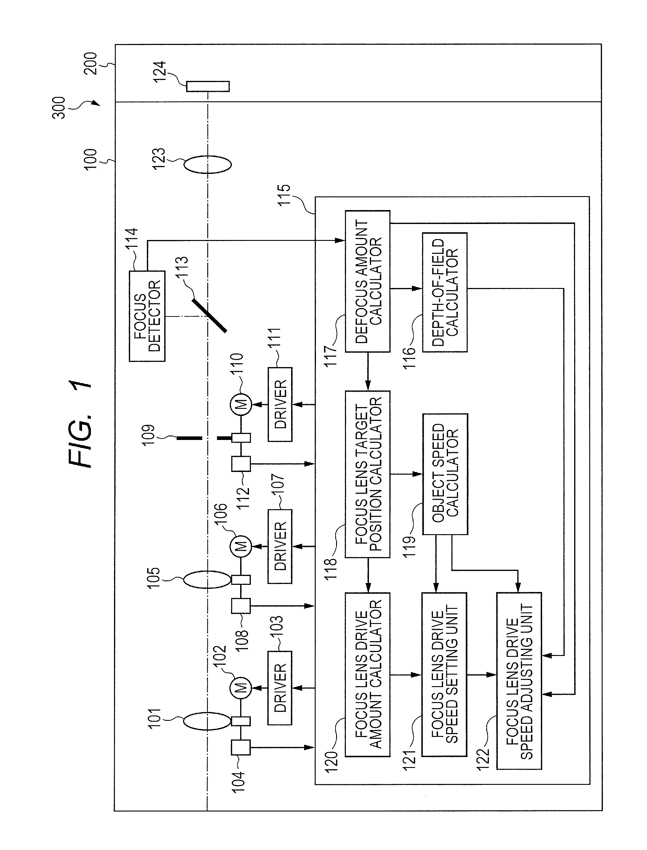
[0022]FIG. 1 illustrates a configuration of a lens apparatus 100 as an autofocus apparatus according to a first embodiment of the present invention. The lens apparatus 100 and a camera apparatus 200 constitute an image pickup apparatus 300. The lens apparatus 100 includes an optical system including a focus lens 101. The lens apparatus 100 moves the focus lens 101 in an optical axis direction so as to change a position of an image plane of the lens apparatus 100.

[0023]The focus lens 101 is connected to a focus motor 102. The focus motor 102 is driven by a focus driver 103 so as to move the focus lens 101 in the optical axis direction. The focus motor 102 and the focus driver 103 constitute a focus lens drive unit. A position of the focus lens 101 is detected by a focus lens position detector 104.

[0024]A zoom lens 105 moves in the optical axis direction so as to change a focal length of the lens apparatus 100. The zoom lens 105 is connected to a zoom motor 106. The zoom motor 106 is ...

second embodiment

[0048]FIG. 7 is a structural diagram of an autofocus apparatus according to a second embodiment of the present invention. Description of the same components as in the first embodiment illustrated in FIG. 1 is omitted, and parts different from those of the first embodiment are described below.

[0049]The autofocus apparatus of the second embodiment includes, in addition to the components in the first embodiment, a threshold changing unit 505, a switch 501 (first changing unit), a switch 502 (second changing unit), a switch 503 (third changing unit), and a switch 504 (fourth changing unit).

[0050]The threshold changing unit 505 changes the thresholds α1, α2, and α3, and the constant γ in Expressions (5), (7), (8), and (11) to arbitrary values input by the switches 501, 502, 503, and 504 as the changing units. Here, the arbitrary values are input by the switches for a simple description, but the switches may be replaced by other units that can set arbitrary values.

[0051]The operation in t...


PUM


Abstract

An autofocus apparatus includes a target position calculator for calculating a focus lens target position based on a defocus amount obtained based on the signal of focus detector of a phase difference detecting type and a focus lens position, a target position memory for storing the target position, a speed calculator for calculating an object speed in an optical axis direction based on a present target position, the previous target position, and time period between calculations of present target position and prior target position, and a lens controller for setting, when the object speed changes, a focus lens drive speed based on the present target position, the focus lens position and the object speed and setting, when the object speed does not change, the focus lens drive speed based on a present drive speed, a present defocus amount, and a previous defocus amount.

Description

BACKGROUND OF THE INVENTION[0001]1. Field of the Invention[0002]The present invention relates to an autofocus apparatus to be used for an optical apparatus such as a television camera lens or a video lens, and more particularly, to an autofocus apparatus to be used for an optical apparatus having an autofocus function and including a phase difference detecting type focus detector.[0003]2. Description of the Related Art[0004]Hitherto, various proposals have been made for autofocus (AF) technology for an image pickup apparatus such as a camera or a video camera. For instance, there is well known an autofocus method in which light beams from an object after passing through different exit pupil areas of an image pickup lens are focused to form an image on a pair of line sensors, and a defocus amount is calculated to drive the image pickup lens.[0005]Japanese Patent Application Laid-Open No. 2001-021794 discloses a method of predicting a future image plane position by using a given funct...

Claims


Application Information

Patent Timeline
Patent Type & Authority Applications(United States)
IPC IPC(8): H04N5/232
CPCH04N5/23212G02B7/34G03B3/10H04N23/672
Inventor MIYAJIMA, SHUNSUKE
Owner CANON KK
Why Eureka
Try Eureka