Lens controller

a technology of a controller and a lens is applied in the field of lenses controllers, which can solve the problems of angle variation associated with a movement of a focus, the inability to perform the same way of viewing angle correction, etc., and achieve the effect of preventing the variation of the view angle associated with a movement of the focus

Active Publication Date: 2007-07-26
FUJIFILM CORP
View PDF8 Cites 9 Cited by
  • Summary
  • Abstract
  • Description
  • Claims
  • Application Information

AI Technical Summary

Benefits of technology

[0009]The present invention is made in view of such a circumstance and intended to provide a lens controller which can prevent a view angle variation associated with a movement of a focus during AF control.
[0010]To achieve the object, a lens controller according to a first aspect of the present invention is characterized in that the lens controller which electrically controls a focus and a zoom of a taking lens includes an AF control device which automatically controls the focus of the taking lens so that a given subject imaged by the taking lens is in focus, and a view angle correction device which keeps an angle of view of the taking lens constant by moving the zoom of the taking lens to prevent a variation of the angle of view associated with a movement of the focus moved by the AF control device.
[0011]According to the present invention, a view angle variation associated with a movement of a focus is prevented even during AF control.
[0014]According to the lens controller in accordance with the present invention, a view angle variation associated with a movement of the focus can be prevented even during AF control.

Problems solved by technology

However, in a case of the AF control, view angle correction cannot be performed in the same way as in the MF control because a position to which the focus is moved cannot be known.
Conventionally, there is a disadvantage that a view angle variation associated with a movement of a focus occurs during AF control because view angle correction is not performed during AF control.

Method used


Image

  • Lens controller
  • Lens controller
  • Lens controller

Examples


Embodiment Construction

[0019]Hereinafter, preferred embodiments for implementing the lens controller according to the present invention will be described in detail with reference to the accompanying drawings.

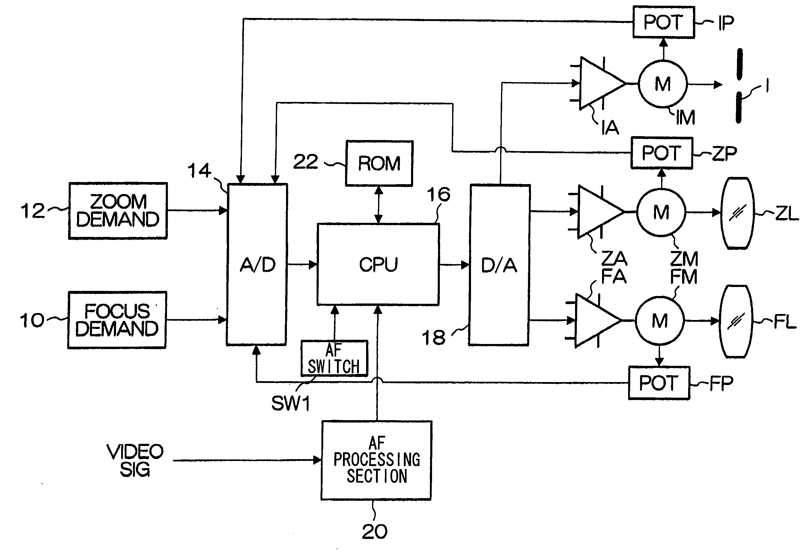
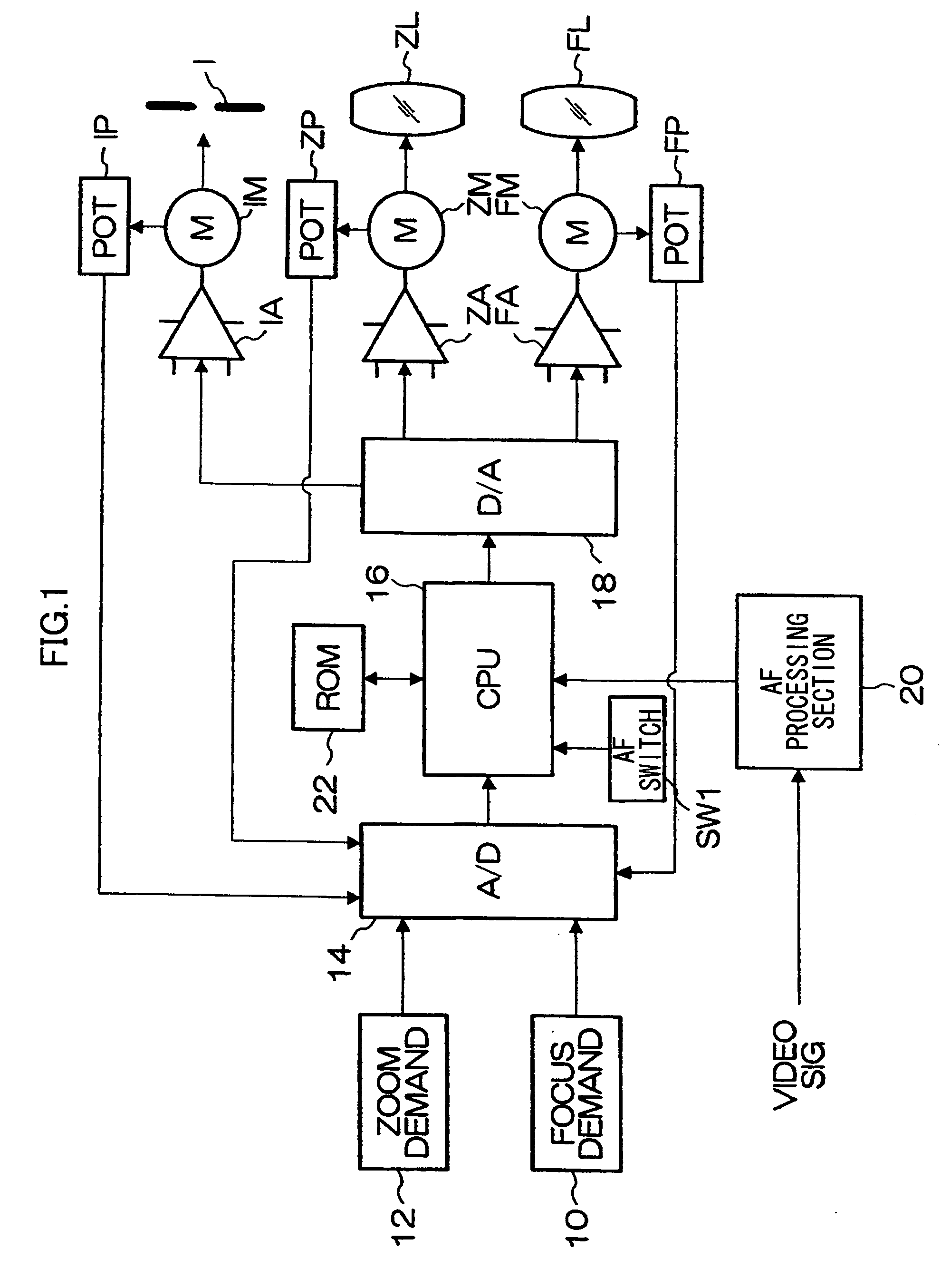
[0020]FIG. 1 is a block diagram which shows a configuration of a lens controller to which the present invention is applied. The lens controller shown in FIG. 1 is a device for controlling a taking lens (an optical system of a lens apparatus) used in a television camera, video camera, or the like. In the taking lens, focus lens(es) FL which moves in the direction of the optical axis for adjusting focus, zoom lens(es) ZL which moves in the direction of the optical axis for adjusting zoom (adjusting a focal length), an iris I which performs a switching action for adjusting a quantity of light, and so on are provided. An object light incident on the taking lens is formed on an imaging surface (imaging plane) of an image pickup element of a camera body (camera head) (not shown) to which the taking lens is ...


PUM


Abstract

The present invention provides a lens controller which electrically controls a focus and a zoom of a taking lens, the lens controller comprising: an AF control device which automatically controls the focus of the taking lens so that a given subject imaged by the taking lens is in focus; and a view angle correction device which keeps an angle of view of the taking lens constant by moving the zoom of the taking lens to prevent a variation of the angle of view associated with a movement of the focus moved by the AF control device; wherein, when the focus is moved by the AF control device, the view angle correction device detects a current position of the focus by a position detecting device, obtains a position of the zoom for preventing the variation of the angle of view based on the detected current position of the focus, and moves the zoom to the obtained position.

Description

BACKGROUND OF THE INVENTION[0001]1. Field of the Invention[0002]The present invention relates to a lens controller, and particularly to a lens controller having an auto focus (AF) function.[0003]2. Description of the Related Art[0004]There is known a television camera, video camera, or the like having an auto focus (AF) function which automatically controls a focus so that a subject is in focus. A method of AF employed in a television camera or video camera is typically a method referred to as a contrast method, which detects a contrast of a subject image based on a picture signal obtained by an image pickup element and controls a focus (focus lens) to maximize the contrast.[0005]Additionally, a phenomenon called a pumping is conventionally known in which, when a focus is moved, an angle of view (focal length) is varied as though zooming is performed even though a zoom is fixed in a taking lens. To prevent such a pumping phenomenon, there is a known lens controller having a view ang...

Claims


Application Information

Patent Timeline
Patent Type & Authority Applications(United States)
IPC IPC(8): G03B17/00
CPCG02B7/102G03B3/10H04N5/23296H04N5/23212G03B13/36H04N23/673H04N23/69
Inventor MORIYA, CHIKATSU
Owner FUJIFILM CORP
Why Eureka
Try Eureka