

Lens barrel
- Summary
- Abstract
- Description
- Claims
- Application Information
AI Technical Summary
Benefits of technology
Problems solved by technology
Method used
Image

Examples
Embodiment Construction
[0040]Selected embodiments of the present technology will now be explained with reference to the drawings. It will be apparent to those skilled in the art from this disclosure that the following descriptions of the embodiments of the present technology are provided for illustration only and not for the purpose of limiting the technology as defined by the appended claims and their equivalents.
[0041]
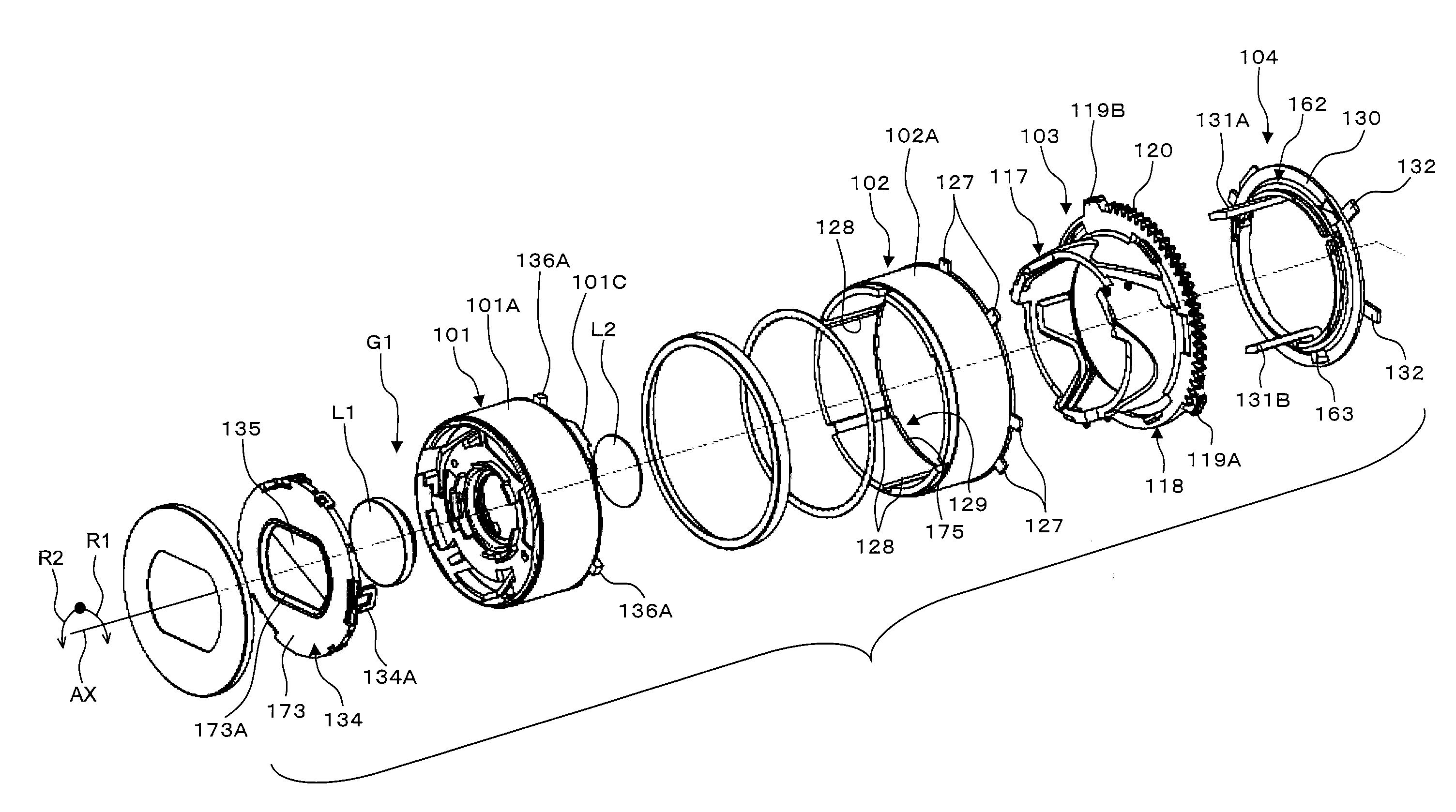
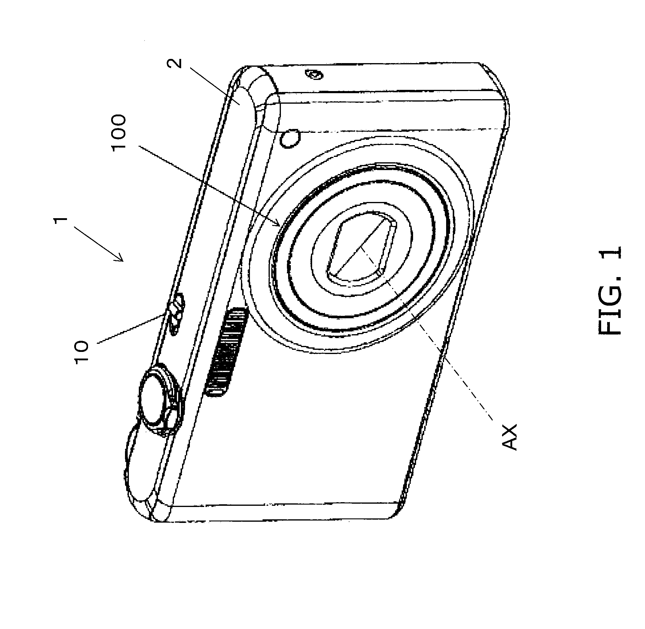
[0042]As shown in FIG. 1, the digital camera 1 comprises a housing 2 and a lens barrel 100 (an example of a lens barrel). When a power switch 10 is used to turn on the power, the lens barrel 100 is deployed from the housing 2 so that imaging is possible.
[0043]The digital camera 1 shown in FIG. 1 is an example of an imaging device. The imaging device may be a digital camera or a film camera. Also, the imaging device may be a camera with which the lens barrel 100 can be removed and exchanged. The imaging device may also be a still camera that primarily captures still pictures. Or, the imagin...
PUM
 Abstract
Description
Claims
Application Information