Separator having a centrifugal drum

a centrifugal drum and separator technology, applied in the direction of centrifuges, food shaping, alcoholic beverage preparation, etc., can solve the problem of problematic product oxygen absorption potential

Active Publication Date: 2013-11-21
GEA MECHANICAL EQUIP
View PDF8 Cites 3 Cited by
  • Summary
  • Abstract
  • Description
  • Claims
  • Application Information

AI Technical Summary

Benefits of technology

[0007]An embodiment according to the present disclosure provides a separator with which it is easily possible to conduct an inert gas into the region of the gripper chambers in the processing of an oxygen-sensitive product in order to prevent that the product will come into contact with the oxygen in this region. In the clarification of beer from yeast, for example, the separator is especially suitable for protecting the beer as the lighter phase with the inert gas from contact with oxygen.
[0008]Although it is also known from DE 20 2007 009 212 to conduct a gas into the region of a drum head between a gripper for a lighter phase and an overflow for discharging a heavier phase, the gas is used for the purpose of displacing the separation zone in the drum. However, in accordance with an embodiment of the present disclosure, for example, it is enabled, in a constructionally simple way, to conduct an inert gas without any high pressure which could cause a displacement of the separation zone into the region between the two grippers. In accordance with an embodiment of the present disclosure, a construction with two gripper chambers and grippers which are disposed radially in a virtually “concentric” fashion with respect to each other has proved to be advantageous.

Problems solved by technology

A potential absorption of oxygen by the product is problematic where sensitive products such as beer are concerned.

Method used


Image

  • Separator having a centrifugal drum
  • Separator having a centrifugal drum
  • Separator having a centrifugal drum

Examples


Embodiment Construction

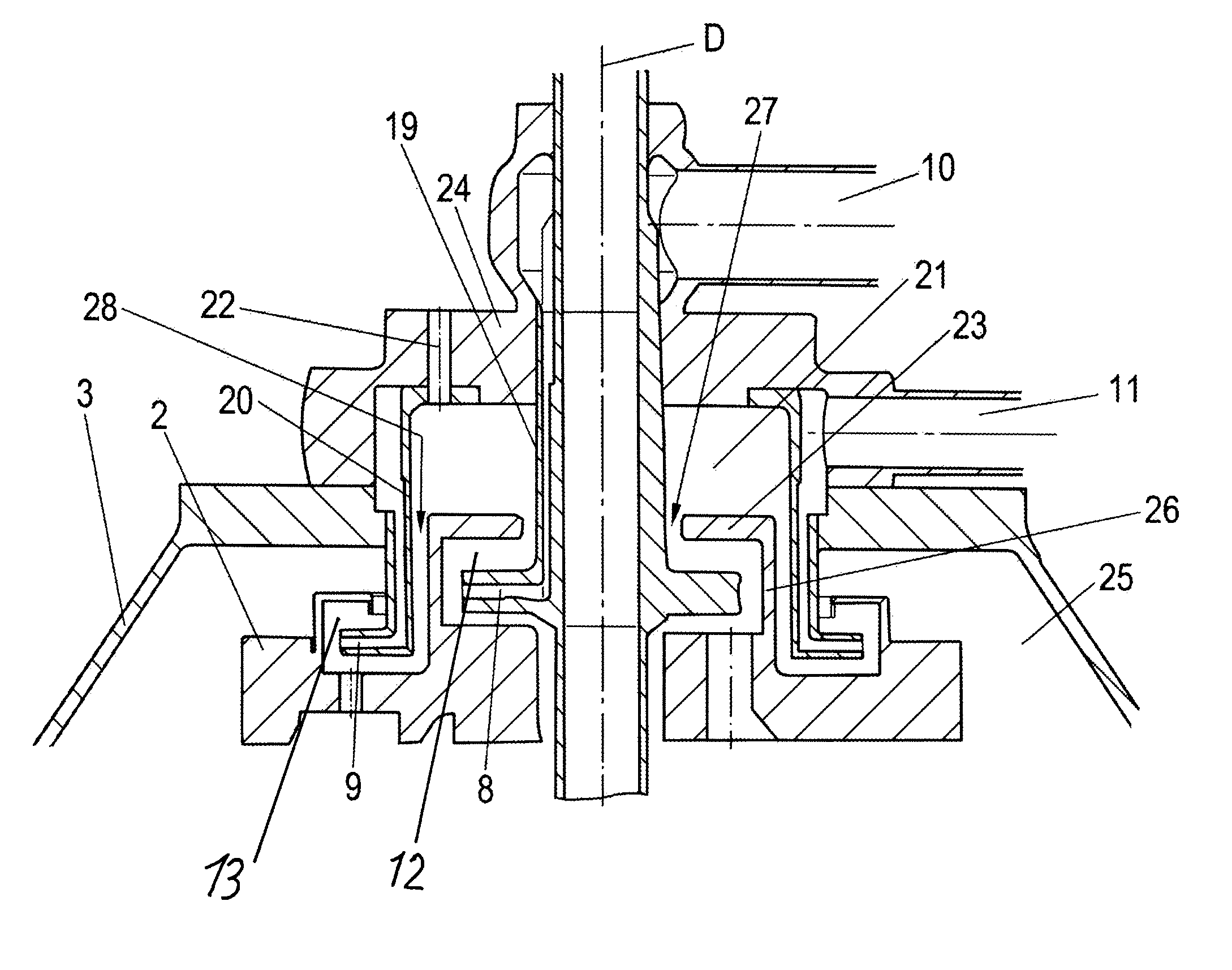
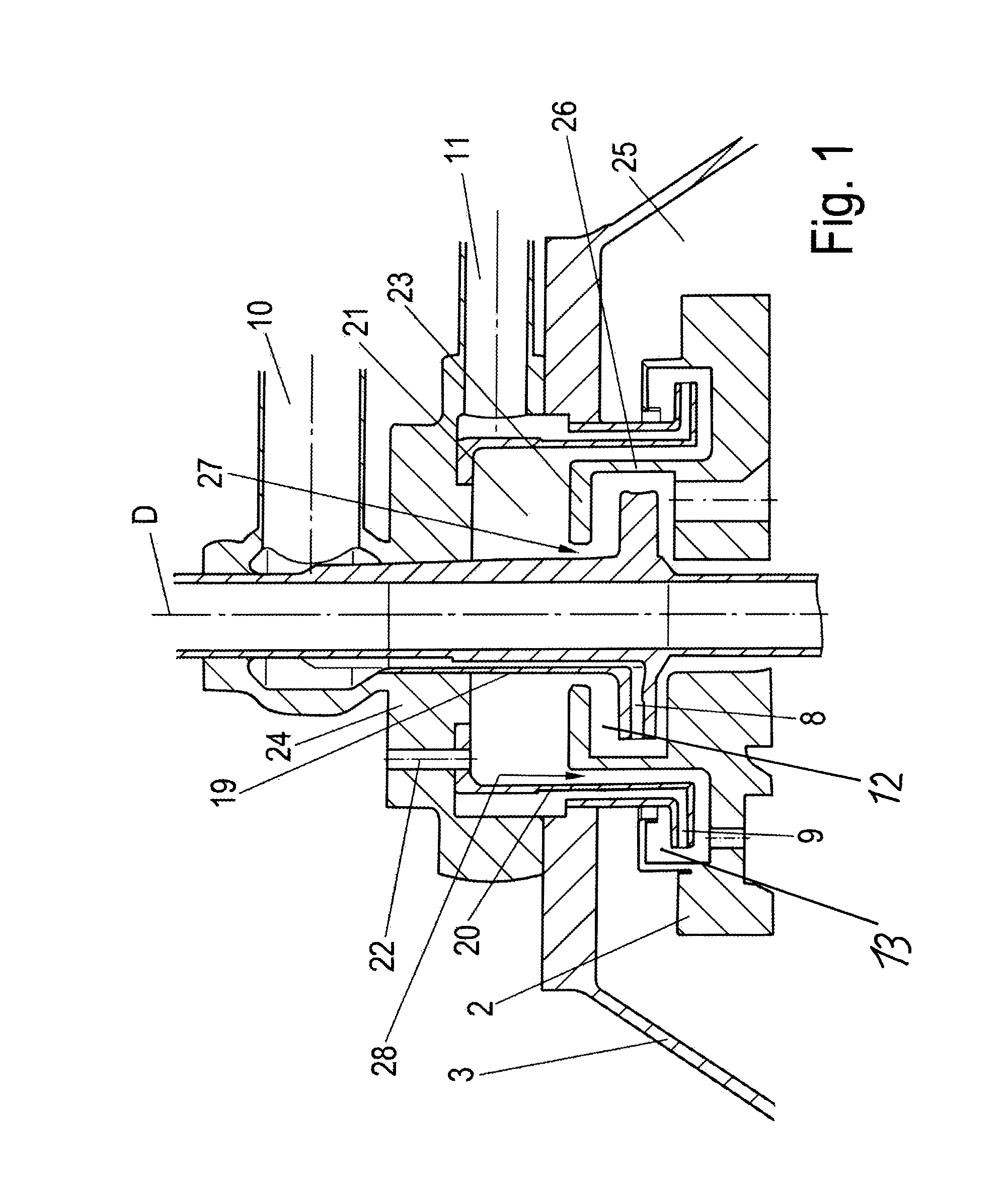
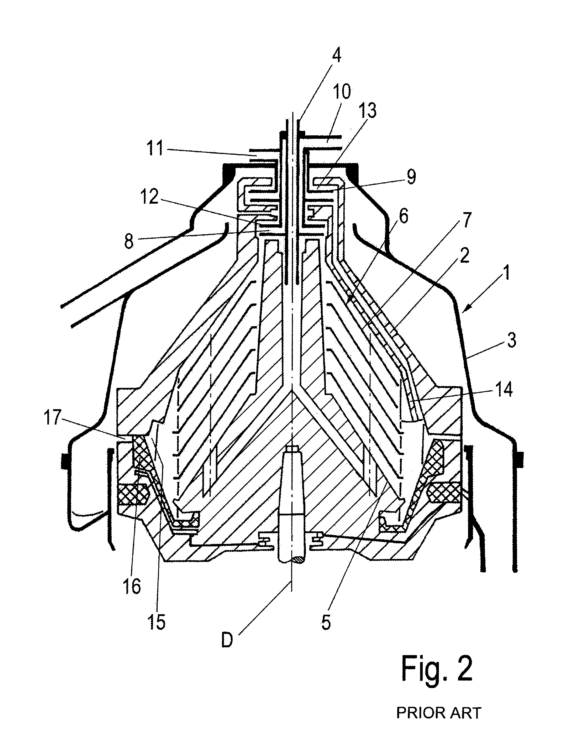
[0016]It should be noted that elements or structural features of the separator 1 of FIG. 2 may also be referred to herein with regard to current embodiments in accordance with the present disclosure related to FIG. 1. Differences may exist between certain structural elements of the known separator 1 in FIG. 2 and the embodiment of the separator 1 according to the present disclosure of FIG. 1.

[0017]The drum 2, has a vertically-oriented drum and has a rotational axis D. Drum 2 includes an inlet tube 4 which does not rotate in operation with the drum 2 and which is guided from above into the drum 2, for example. A distributor 5 is connected downstream of the inlet tube 4, by which the material to be centrifuged can be guided into the drum 2. A disc stack 6, including a plurality of conical discs 7, is arranged in the drum 2.

[0018]The discharge of fluid phases from the drum 2, of which there are two, for example, occurs via two peeling discs or grippers 8, 9, to which discharge lines 10...


PUM


Abstract

A separator includes a rotatable drum having a vertical rotational axis, a disk stack arranged in the drum, an inner gripper and an outer gripper that do not rotate with the drum are configured to discharge mutually-separated liquid phases. A discharge line is assigned to each gripper and is arranged in an associated gripper chamber of the drum. The inner gripper includes an inner gripper shaft and the outer gripper includes an outer gripper shaft both of which shafts protrude axially from the drum. Each associated gripper chamber, with its associated gripper, revolves on different radii with respect to the rotational axis such that a chamber is formed radially between an outer circumference of the inner gripper shaft and an inner circumference of the outer gripper shaft. A fluid is insertable into the chamber through a channel, which fluid is pressable from the chamber into the gripper chambers.

Description

CROSS-REFERENCE TO RELATED APPLICATION[0001]This application is a national stage of International Application PCT / EP2011 / 062796, filed Jul. 26, 2011, and claims benefit of and priority to German Patent Application No. 10 2010 032 859.6, filed Jul. 30, 2010, the content of which Applications are incorporated by reference herein.BACKGROUND AND SUMMARY[0002]The present disclosure relates to a separator including a rotatable drum having a vertical rotational axis and a disk stack arranged in the drum. Also included are an inner gripper and an outer gripper that do not rotate with the drum and are configured to discharge mutually-separated liquid phases. A discharge line is assigned to each gripper and is arranged in an associated gripper chamber of the drum. The inner gripper includes an inner gripper shaft and the outer gripper includes an outer gripper shaft both of which shafts protrude axially from the drum.[0003]Reference is hereby made to DE 18 02 676, U.S. Pat. No. 4,417,885 and ...

Claims


Application Information

Patent Timeline
Patent Type & Authority Applications(United States)
IPC IPC(8): B04B11/02A23L2/70
CPCB04B11/02A23L2/70B04B11/082C12H1/061C12H1/14B04B1/20B04B5/12B04B11/08
Inventor HERBERG, WOLF-DIETRICHWAUBKE, CARSTEN
Owner GEA MECHANICAL EQUIP
Why Eureka
Try Eureka