
Testing system

a testing system and testing technology, applied in the field of testing systems, can solve problems such as increasing testing costs

Inactive Publication Date: 2013-11-21
HONG FU JIN PRECISION IND (SHENZHEN) CO LTD +1
View PDF2 Cites 3 Cited by
  • Summary
  • Abstract
  • Description
  • Claims
  • Application Information

AI Technical Summary

Benefits of technology

The patent text describes a problem in testing systems where many differing types of oscillographs are needed and each requires a special computer bus card to connect, which increases testing costs. The technical effect is to provide a solution that reduces the need for multiple bus cards and speeds up the testing process.

Problems solved by technology

Thus, the computer needs to employ a special bus card to connect to the oscillograph, which increases costs of testing.

Method used


Image

  • Testing system
  • Testing system

Examples


Embodiment Construction

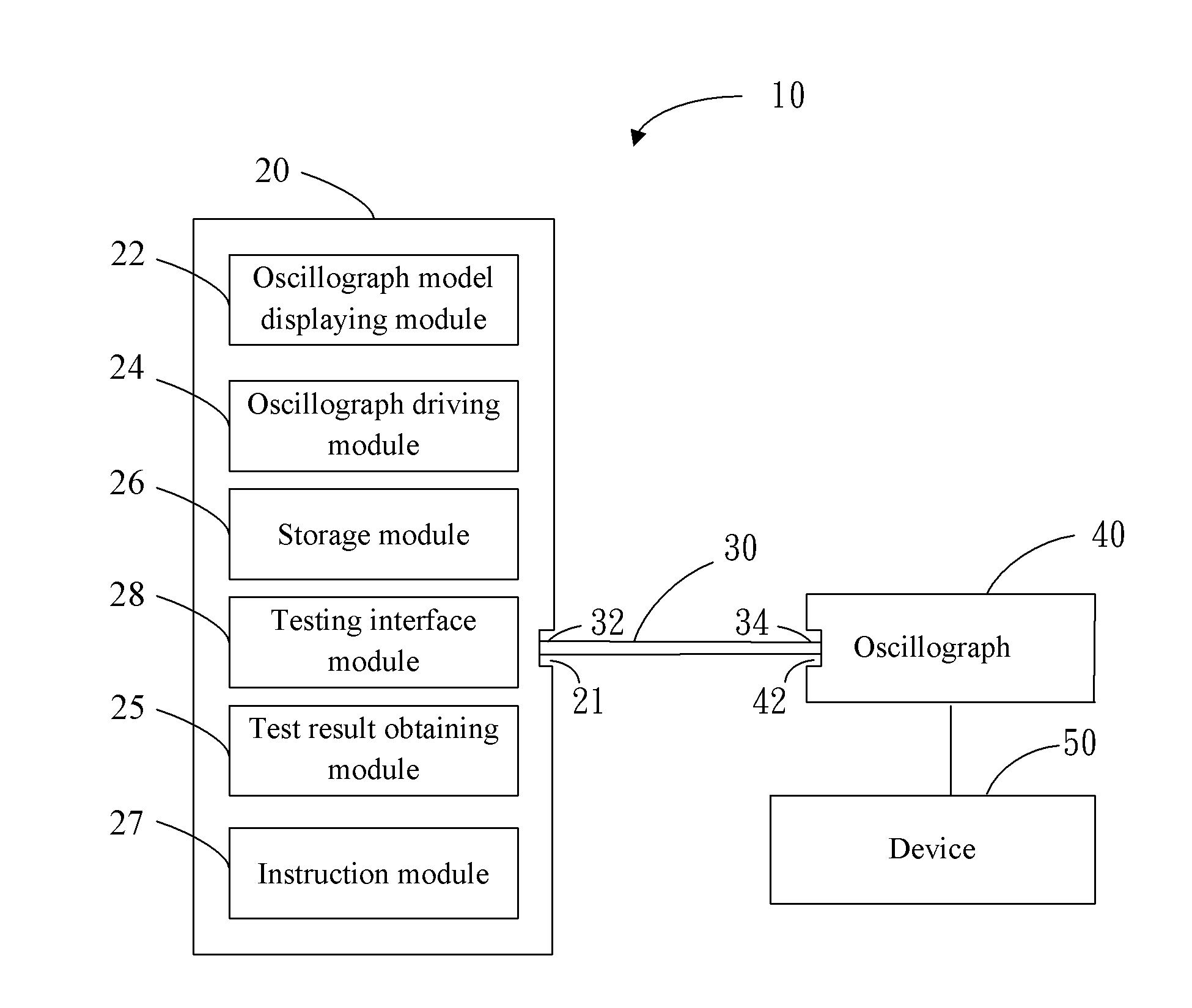
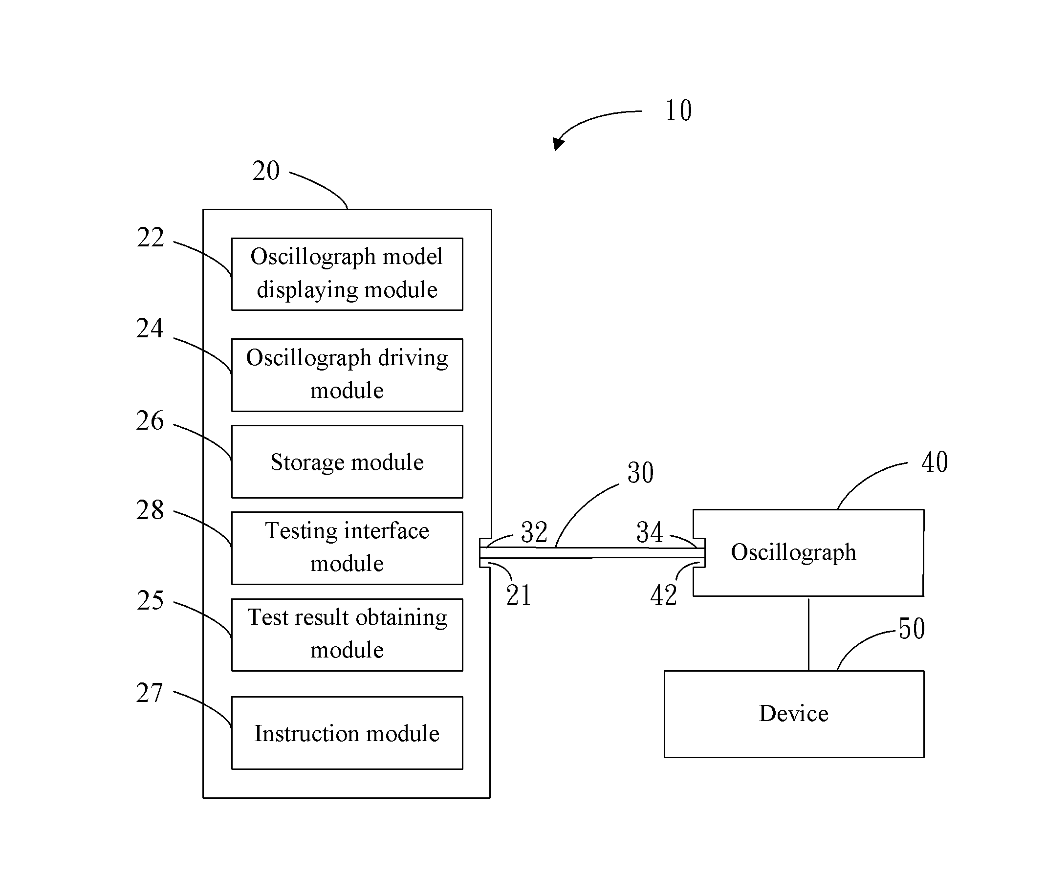
[0007]Referring to the drawing, a testing system 10 for testing a device 50 according to an exemplary embodiment includes a computer 20, a connection cord 30 and a number of different models of oscillographs 40. Each oscillograph 40 has a general purpose interface bus (GPIB) port 42. The connection cord 30 has a universal serial bus (USB) connector 32 at a first end, and a GPIB connector 34 at an opposing second end for selectively connecting to a GPIB port 42 of one of the oscillographs 40. The computer 20 has a USB port 21 for connection with the USB connector 32 of the connection cord 30. The computer 20 can be connected to the oscillographs 40 in turn by the connection cord 30.

[0008]The computer 20 includes an oscillograph model displaying module 22, an oscillograph driving module 24, a storage module 26, a testing interface module 28, and a test result obtaining module 25.

[0009]The oscillograph model displaying module 22 is configured for displaying a number of oscillograph mod...


PUM


Abstract

A testing system includes a computer, a connection cord, and a number of oscillographs. The each oscillograph has a GPIB port. The computer has a USB port. The connection cord has a USB connector for connection with the USB port and a GPIB connector for selectively connecting to a GPIB port of one of the oscillographs. The computer includes an oscillograph model displaying module, an oscillograph driving module, a storage module, and a testing interface module. The oscillograph model displaying module displays a number of oscillograph models for a user to select. The oscillograph driving module loads an oscillograph driver corresponding to the selected oscillograph model. The storage module stores a plurality of codes associated with a number of testing functions for different oscillographs. The testing interface module transmits the codes to the oscillograph, thereby driving the oscillograph to perform the associated testing functions to test a device.

Description

BACKGROUND[0001]1. Technical Field[0002]The present disclosure relates to a testing system, especially to a testing system having an oscillograph.[0003]2. Description of Related Art[0004]Oscillographs are widely used in testing systems. Often many oscillographs of different types are needed, and each oscillograph is connected to a computer via a General Purpose Interface BUS. Thus, the computer needs to employ a special bus card to connect to the oscillograph, which increases costs of testing.BRIEF DESCRIPTION OF THE DRAWINGS[0005]Many aspects of the embodiments can be better understood with reference to the following drawings. The components in the drawings are not necessarily drawn to scale, the emphasis instead being placed upon clearly illustrating the principles of the embodiments. Moreover, in the drawings, like reference numerals designate corresponding parts throughout the several views.[0006]The drawing is a block diagram of a testing systemDETAILED DESCRIPTION[0007]Referri...

Claims


Application Information

Patent Timeline
IPC IPC(8): G01R13/02
CPCG01R13/0254G01R31/31907G01R13/02G01R19/2516
Inventor XU, ZHI-GANG
Owner HONG FU JIN PRECISION IND (SHENZHEN) CO LTD
Learn More