
Two-way protective pad construction

Inactive Publication Date: 2013-11-28
WARRIOR SPORTS INC
View PDF59 Cites 25 Cited by
  • Summary
  • Abstract
  • Description
  • Claims
  • Application Information

AI Technical Summary

Benefits of technology

The patent describes a protective pad that has a rigid shell and a gasket made of a high-density material. The pad is designed to absorb and dissipate impact forces, providing protection to the wearer and the person or item impacting them. The pad acts like a trampoline or two-way spring, effectively absorbing energy and dissipating impact forces. This design can offer effective protection in a variety of situations.

Problems solved by technology

Sporting activities, such as hockey, lacrosse, baseball, basketball, football, soccer, biking, motorcycling and other activities all can lead to falls, collisions and impacts, which can cause pain, injury and damage to unprotected parts of the body.
The two foam layers act as a cushion and provide comfort; however, they frequently attain their compression limit, bottoming out and doing little to attenuate further transferred impact forces.
Therefore, as the contact area increases, the pressure decreases, and so does the risk of injury.
The wearer may feel the pressure from the impact, but it typically is not enough to cause injury.
The reason the present protective padding described above works for the wearer, is the same reason that it is ineffective for protecting opponents or other players during collisions with the wearer of the protective padding.
The foam, as mentioned above, does not provide much cushioning between the wearer and the other player or person, particularly where the force exceeds the compressive strength and the foam bottoms out.
With this reduced shock absorption, the player or person impacting or being impacted by the wearer of the protective padding usually experiences a great deal of pressure in a very localized area.
As a result, that other player or person can be injured by the impact, even though the wearer of the protective padding is not injured.

Method used


Image

  • Two-way protective pad construction
  • Two-way protective pad construction
  • Two-way protective pad construction

Examples


Embodiment Construction

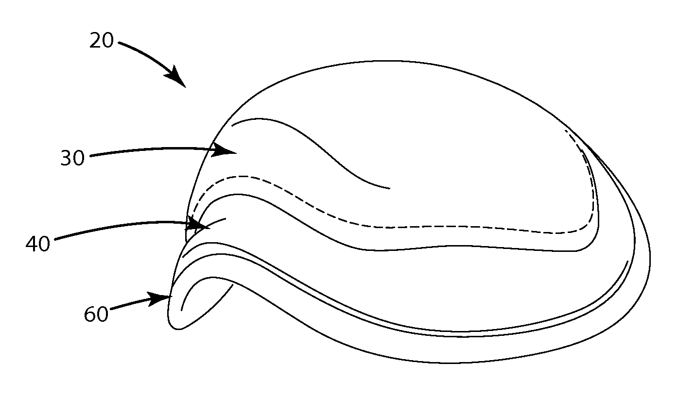
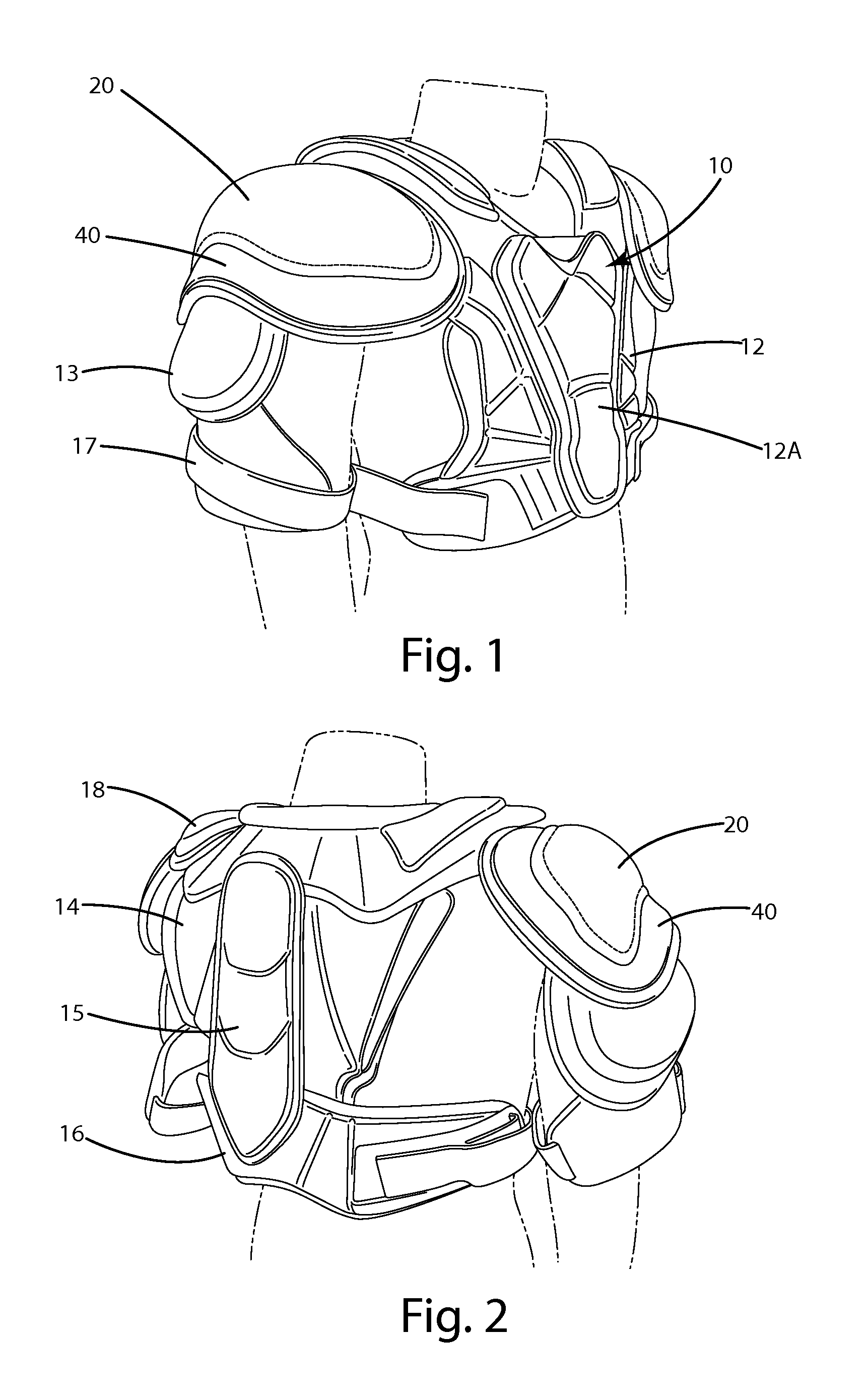
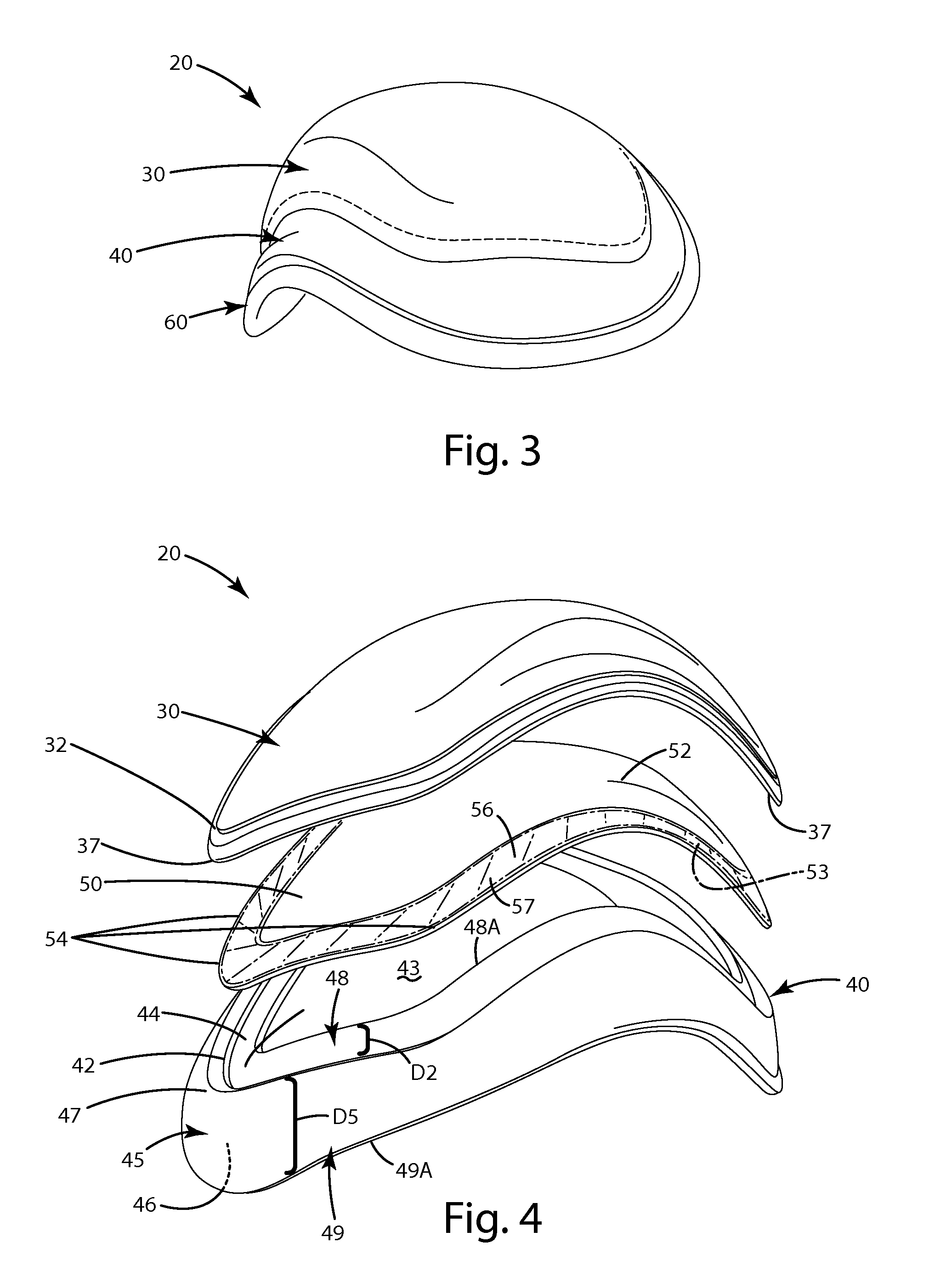
[0044]FIGS. 1-8 illustrate a shoulder pad system 10 including a current embodiment of the protective pad 20. In general, the shoulder pad system 10 includes a pair of shoulder caps 20, also referred to as shoulder pads or protective pads, which are joined with a chest protector 12 and back protector 14. The shoulder pad system 10 can also include a sternum protector 12A associated with the chest protector 12, and a spine protector 15 associated with the back protector 14. The shoulder system 10 can include rib protectors 16 and collar bone protectors 18. Of course, the protector pad 20, in the form of a shoulder pad in the pad system 10, can be in a variety of different configurations and can take on a variety of different pad formations. Although described in conjunction with a shoulder pad and elbow pad, as noted above, the protective pad 20 can be incorporated into knee pads, shin guards, wrist pads, gloves, thumb protectors, digit protectors, leg pads, ankle pads, body armor, he...


PUM


Abstract

A protective pad including a rigid shell bounded by a perimeter and a gasket engaging the perimeter so that forces applied to the shell are dissipated through the gasket before transferring to a wearer of the protective pad. The rigid shell cooperates with the gasket to provide a trampoline effect or two way spring. This effectively absorbs shock from forces generated by the opponent, so that the wearer and a colliding opponent both encounter reduced forces. The shell can bow outwardly to form a cavity above the wearer when the gasket is placed adjacent the wearer, which can prevent the rigid shell from bottoming out against the wearer upon impact. The protective pad can be implemented in a thumb protector including a stopper disposed between adjacent rigid shells covering proximal and distal portions of a digit. The stopper can engage the shells and effectively prevent hyperextension of the digit.

Description

BACKGROUND OF THE INVENTION[0001]The present invention relates to protective equipment that shields forces, which are exerted on a wearer, and more particularly, to a multi-layered padding construction that provides minimal bulk and impediment to movement, yet maximizes protective coverage and protection to both the wearer, and optionally another person impacting the protective equipment.[0002]Protective padding is used to protect its wearer from injury or from experiencing an impact due to applied forces. The increased popularity of physical sports has increased the need for personal protective padding. Sporting activities, such as hockey, lacrosse, baseball, basketball, football, soccer, biking, motorcycling and other activities all can lead to falls, collisions and impacts, which can cause pain, injury and damage to unprotected parts of the body.[0003]Conventional protective padding, however, uses “one-way” padding constructions. This means they are primarily designed to protect ...

Claims


Application Information

Patent Timeline
IPC IPC(8): A41D13/015
CPCA41D13/015A63B71/08A63B71/12A63B71/1225A63B71/1291A63B71/141A63B2071/1208
Inventor PAUL, MICHEL S.JAJKO, OLIVIER C.ARPIN, VINCENT
Owner WARRIOR SPORTS INC
Learn More