Hammer test bench

a test bench and hammer technology, applied in the field of test benches, can solve the problems of kinetic energy being converted into destructive actions, the scale of size and component design generally not suitable, and the failure of the dissipating device, so as to preserve the structural integrity of the pneumatic air bag assembly, dissipate the impact force of the hammer upon test firing, and dissipate the impact force of the hammer

Active Publication Date: 2010-10-14
CLEVELAND BROS EQUIP
View PDF9 Cites 8 Cited by
  • Summary
  • Abstract
  • Description
  • Claims
  • Application Information

AI Technical Summary

Benefits of technology

[0011]The present invention provides a hammer test bench and a method for testing large industrial hammers and, in particular, hydraulic hammers which may be of massive size and operating force. In accordance with an embodiment of the present invention, there is provided a test bench with a movable mounting deck assembly for securing a large industrial hammer on the test bench and mechanically moving and securely holding the hammer into a firing position with the tool of the hammer against a load cell assembly, which is capable of dissipating the repetitive impact force of the hammer upon test firing. The load cell assembly is comprised of an impact receptor mounted to a pneumatic air bag assembly secured within a support carriage which allows the pneumatic air bag assembly to contract upon impact of the hammer tool on the impact receptor and then rebound to expand to its original configuration to dissipate the impact force of the hammer. The pneumatic air bag assembly is equipped with a gauge regulator assembly that allows the air pressure within the air bag assembly to be adjusted to accommodate the size of the hammer being tested and with pressure relief valves that protect the air bag assembly from being over inflated. The support carriage allows the pneumatic air bag assembly to contract and expand but holds the air bag assembly in a linear position so as to keep the impact receptor aligned with the hammer tool to preserve the structural integrity of the pneumatic air bag assembly. The height of the load cell assembly may be adjusted by raising or lowering the support carriage to align the hammer tool with the center of the impact receptor. The energy needed for movement of the mounting deck assembly and the energy needed for the firing of the hammer are generally supplied separately by a power unit which can be operated by remote control.

Problems solved by technology

During operation, the kinetic energy of the percussion piston when it strikes a tool is introduced via the tool and the tool tip into the material to be processed and the kinetic energy is converted into destructive actions.
However, these test benches by virtue of their scale of size and component design generally are not suitable for testing the larger industrial hammers and, in particular, hydraulic hammers because of the massive size and force generated by hydraulic hammers in comparison to hand held pneumatic hammers.
Most notably, these prior art devices employ an impact dissipating device that is insufficient to withstand the impact force of a large hammer and if used with a large industrial hammer the impact of the blow would not only cause the dissipating device to fail within a few blows but would also reflect the impact energy backwards through the frame of the test bench and the hammer securing mechanism so as to cause failure of the apparatus.
However, fluid-containing dissipating devices are not well suited for the repetitive and strong impact force of large industrial hammers because fluid rebounds relatively slowly and also would develop friction which would cause the unit to become hot and possibly fail.
Hydraulic hammers cannot be “dry fired” or test fired without impact against a resisting surface without causing damage to the mechanism.
For this reason, it has not been possible to test fire a hydraulic hammer after servicing the unit without returning it to the field for actual in-service testing.

Method used


Image

  • Hammer test bench
  • Hammer test bench
  • Hammer test bench

Examples


Embodiment Construction

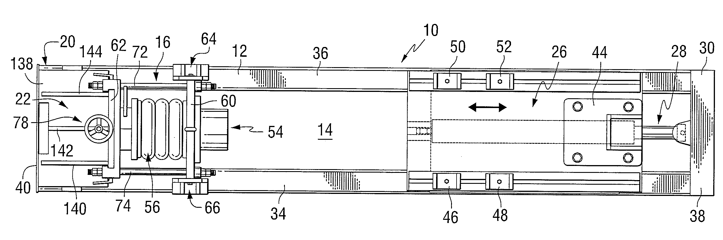
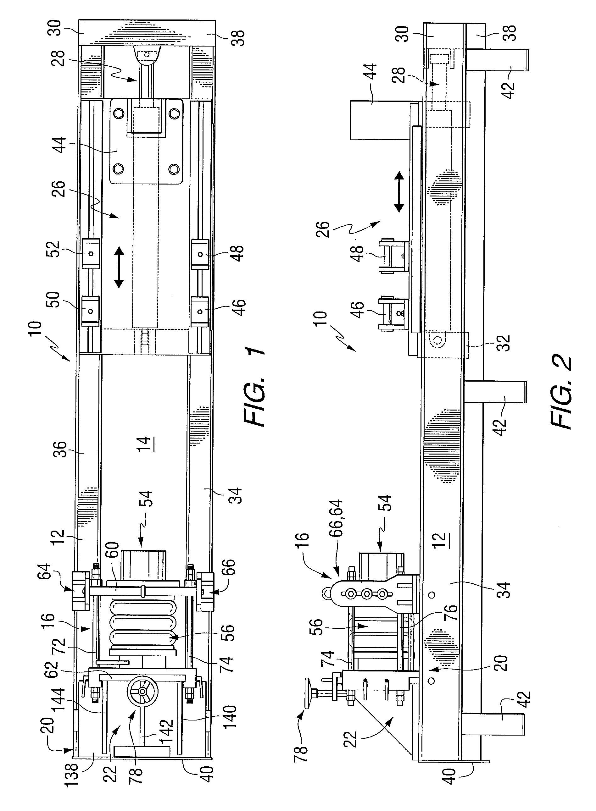
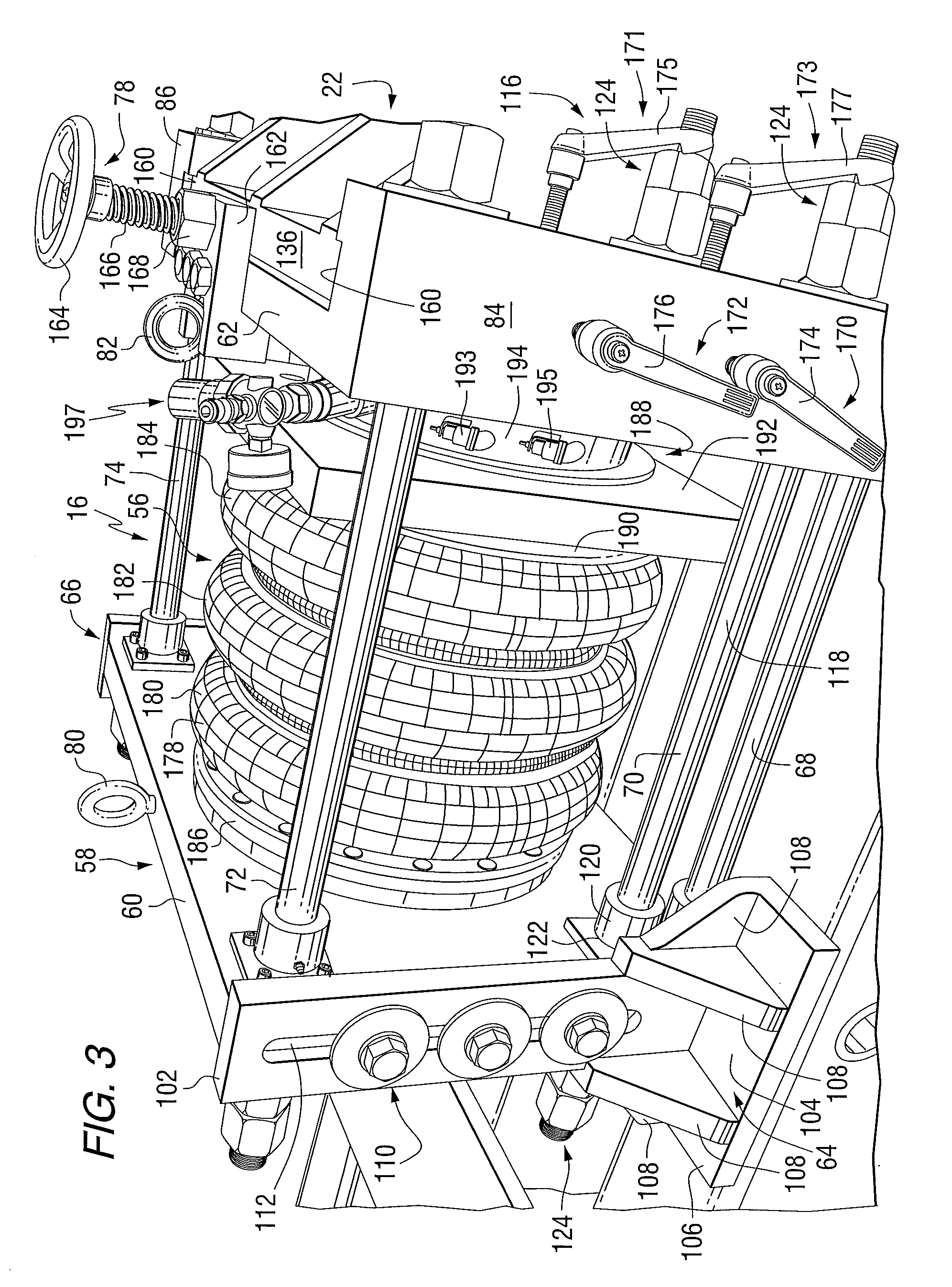
[0024]Referring first to FIGS. 1 and 2, there is illustrated, in general, a hammer test bench 10 for test firing large industrial hammers, and in particular, hydraulic hammers without the hammer being fired in actual field use. Hammer test bench 10 comprises a bench frame 12 with an open center 14 (FIG. 1), a load cell assembly 16 attached to the rear end 20 of bench frame 12 by a tailstock 22 which is fixedly mounted on the bench frame 12; and a mounting deck assembly 26 which positions the hammer and hammer tool for making contact with the load cell assembly 16 by operation of a hydraulic positioning cylinder assembly 28 located within mounting deck assembly 26 as shown in FIG. 2. Mounting deck assembly 26 secures a hammer to be tested. As better shown in FIG. 2, hydraulic positioning cylinder assembly 28 is attached to the fore end 30 of bench frame 12 and to the rear end 32 of mounting deck assembly 26 for reciprocating mounting deck assembly 26 toward and away from load cell as...


PUM

PropertyMeasurementUnit
lengthaaaaaaaaaa
weightaaaaaaaaaa
lengthaaaaaaaaaa

Abstract

A test bench for testing a hammer and hammer tool comprising: a bench frame; a load cell assembly mounted on the bench frame for absorbing the impact delivered by the hammer; and a movable mounting deck for securing the hammer to the bench frame and for moving the hammer with the hammer tool into a test firing position against the load cell assembly and delivering an impact force against the load cell assembly. The load cell assembly comprises a pneumatic air bag assembly constructed to dissipate the impact force of the hammer. Other aspects include a load cell assembly for testing a hammer and hammer tool and a method for test firing a hammer tool. Hydraulic hammers generating forces between 200 ft-lb and 12,000 ft-lb can be adequately test fired.

Description

CROSS REFERENCE TO RELATED APPLICATION[0001]This application claims priority to U.S. Provisional Application Ser. No. 61 / 190,449 filed Aug. 28, 2008, which is incorporated herein by reference.FIELD OF THE INVENTION[0002]This invention relates to a test bench for test firing industrial hammers, such as large industrial hammers and, in particular, to hydraulic hammers without the hammer being fired in actual field use.BACKGROUND INFORMATION[0003]Large industrial hammers are, for example, percussion tools or impact vibrators and include pneumatic hammers, which are powered by compressed air, and hydraulic hammers, which are powered by a liquid.[0004]Pneumatic hammers tend to be of smaller size and striking force than hydraulic hammers. An example of a typical pneumatic hammer is a jack hammer which is hand-held while in use, is approximately two to three feet in length and may weigh up to approximately 60 pounds. A jack hammer may deliver between approximately 900 to 1,600 blows per mi...

Claims


Application Information

Patent Timeline
Patent Type & Authority Applications(United States)
IPC IPC(8): G01L25/00
CPCB25D9/005
Inventor TINKER, JOHNWRIGHT, STEVEN
Owner CLEVELAND BROS EQUIP
Why Eureka
Try Eureka