Chain conveyor system

a conveyor system and chain technology, applied in the direction of conveyor parts, rollers, transportation and packaging, etc., can solve the problems of difficult to release or separate the articles, the chain conveyor system generates noise, and the permanent magnet is not replaced or damaged, so as to avoid damage and vibration noise, smooth release the attraction of the articles, and the effect of enlarge the rang

Active Publication Date: 2014-07-15
TSUBAKIMOTO CHAIN CO
View PDF6 Cites 3 Cited by
  • Summary
  • Abstract
  • Description
  • Claims
  • Application Information

AI Technical Summary

Benefits of technology

[0026]According to the first aspect of the chain conveyor system of the invention, because the chain conveyor system comprises the conveyor chain having the plurality of synthetic resin link modules each having the conveying surface and the link pins for linking the synthetic resin link modules with each other in the chain longitudinal direction and the sprockets that engage with and turn the conveyor chain, the synthetic resin link modules of the conveyor chain synergistically exhibit attractive force and impact absorbing force and absorb impacts and vibrations of the metallic magnetic articles that are otherwise liable to be generated during conveyance of the articles. Therefore, it is possible not only to convey the articles by securely attracting and retaining the articles even on a conveyor line inclined upward or downward or on a slippery wet conveyor line, but also to avoid damages and vibration noise which would otherwise be generated by impacts of the metallic magnetic articles.
[0027]Because the conveyor chain further comprises the magnet-piece-accommodating chambers formed within the synthetic resin link modules and the article-attracting magnet pieces that are accommodated respectively within the magnet-piece-accommodating chambers and that move from the chain inner circumferential side to the chain outer circumferential side within the magnet-piece-accommodating chambers to attract and retain the articles on the conveying surfaces and because the article-separating means disposed on the inner circumferential surface of the conveyor chain for separating the articles attracted to the synthetic link modules comprises the article-separating magnet pieces that separate the articles attracted to the synthetic resin link modules by attracting the article-attracting magnet pieces within the magnet-piece-accommodating chambers from the chain outer circumferential side to the chain inner circumferential side within the magnet-piece-accommodating chambers, the article-attracting magnet pieces move between the chain outer circumferential side where the article-attracting magnet pieces attract the metallic magnetic articles and the chain inner circumferential side where the article-separating magnet pieces attract the article-separating magnet pieces within the magnet-piece-accommodating chambers and thus forcibly attract and separate the articles. Accordingly, it is possible to arbitrarily switch the article-attracting and non-attracting states.
[0028]Furthermore, because the article-separating means extends to the conveying area of the conveyor chain, the article-separating magnet pieces can release the attraction between the articles and the article-attracting magnet pieces sequentially within the conveying area. Therefore, the chain conveyor system can smoothly release the attraction of the articles in tranferring the articles to a succeeding conveyor line or in sampling the articles by enlarging a range for forcibly separating the article-attracting magnet pieces from the articles as necessary to separate the articles.
[0029]According to the second aspect of the chain conveyor system of the invention, because the article-separating means is assembled to the rotary shaft of the sprocket that turns the conveyor chain and extends from the terminal discharge area to the preceding straight discharge area of the conveyor chain, the article-separating magnet pieces can release the attraction between the articles and the article-attracting magnet pieces sequentially between the terminal discharge area and the preceding straight discharge area corresponding to engagement and disengagement states of the conveyor chain and the sprocket.
[0030]Therefore, it is possible to enlarge the range where the article-attracting magnet pieces are forcibly separated from the articles as necessary to separate the articles, to securely avoid the articles from being unintentionally attracted in the terminal discharge area and to securely transfer the articles to the succeeding conveyor line and the like, as compared to a case when the article-separating means is provided coaxially with the sprocket, i.e., only in the terminal discharge area of the conveyor chain.
[0031]According to the third aspect of the chain conveyor system of the invention, because the article-separating magnet pieces of the article-separating means are disposed respectively so as to face to the article-attracting magnet pieces of the synthetic resin link modules and the article-separating magnet pieces of the article-separating means and the article-attracting magnet pieces of the synthetic resin link modules face orderly with each other and attract with each other, it is possible to smoothly transfer the articles by exhibiting both attractive forces in maximum and steadily in separating the articles without causing any phase shift in separation timing of the article-separating means.

Problems solved by technology

However, because the large number of attractive magnet units is disposed on the outer circumferential side of the chain base in the prior art chain conveyor system using the magnet-backed chain, there have been problems that not only do the attractive magnet units come in contact directly with the metallic magnetic articles, thus displacing or damaging the permanent magnets, but also the chain conveyor system generates noise due to the contact or impact by the articles on the magnet units.
Still more, because the attractive magnet units continue to be directly in contact with the metallic magnetic articles and to exhibit their strong attractive force even in a terminal discharge area of the conveying run of the prior art chain conveyor system, it often has been difficult to release or separate the articles, posing a serious hindrance in transferring the articles, due to the strong attractive force of the attractive magnet units in transferring the articles to a succeeding conveyor line.
There has been also another problem that it becomes difficult to remove the articles for sampling against the strong attractive force of the attractive magnet unit when it is desired to sample the articles in an inclined straight conveying area between the feed end and the terminal discharge end of the conveyor run, thus increasing a burden when sampling the articles within the inclined straight conveying area.

Method used


Image

  • Chain conveyor system
  • Chain conveyor system
  • Chain conveyor system

Examples


first embodiment

[First Embodiment]

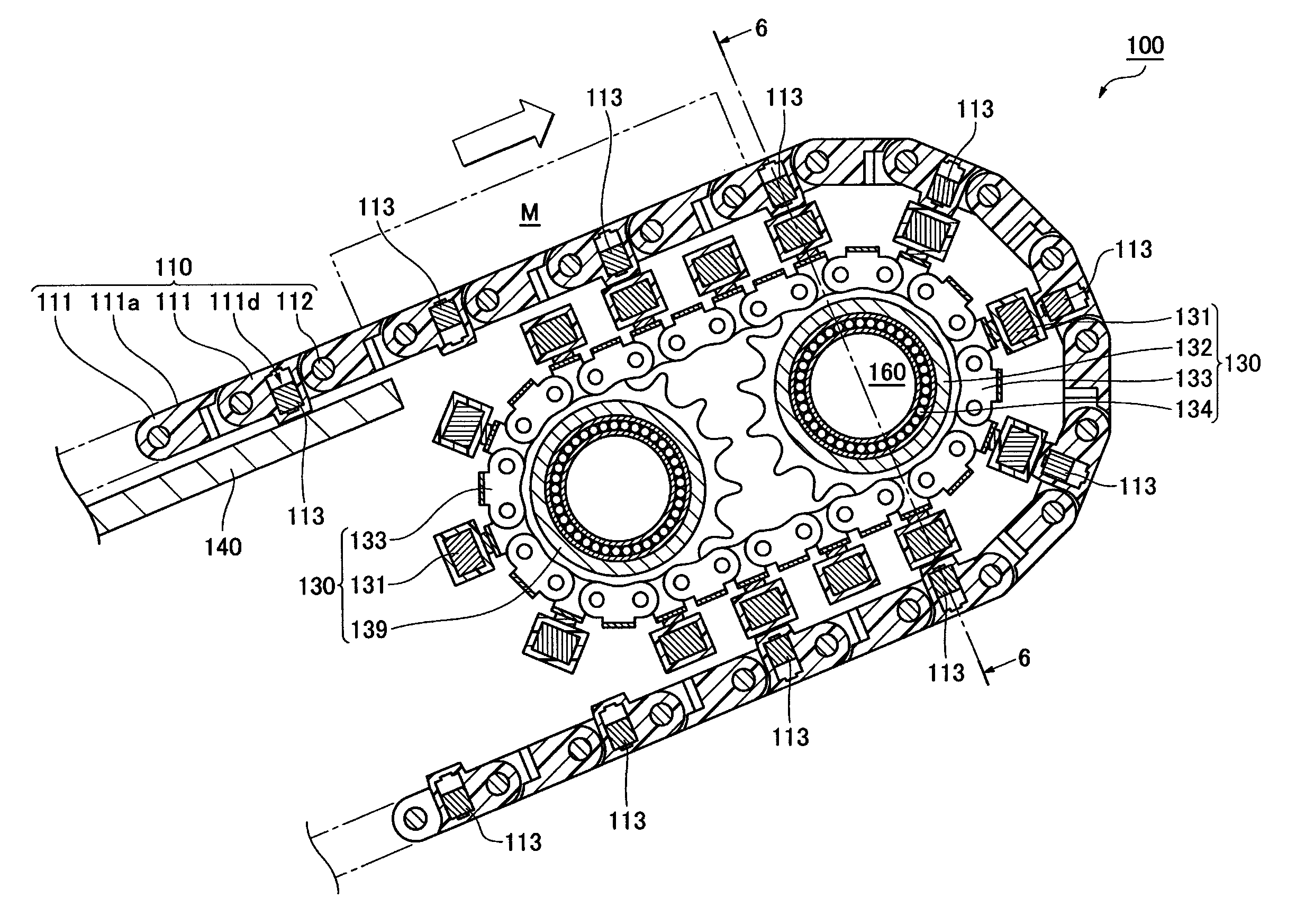
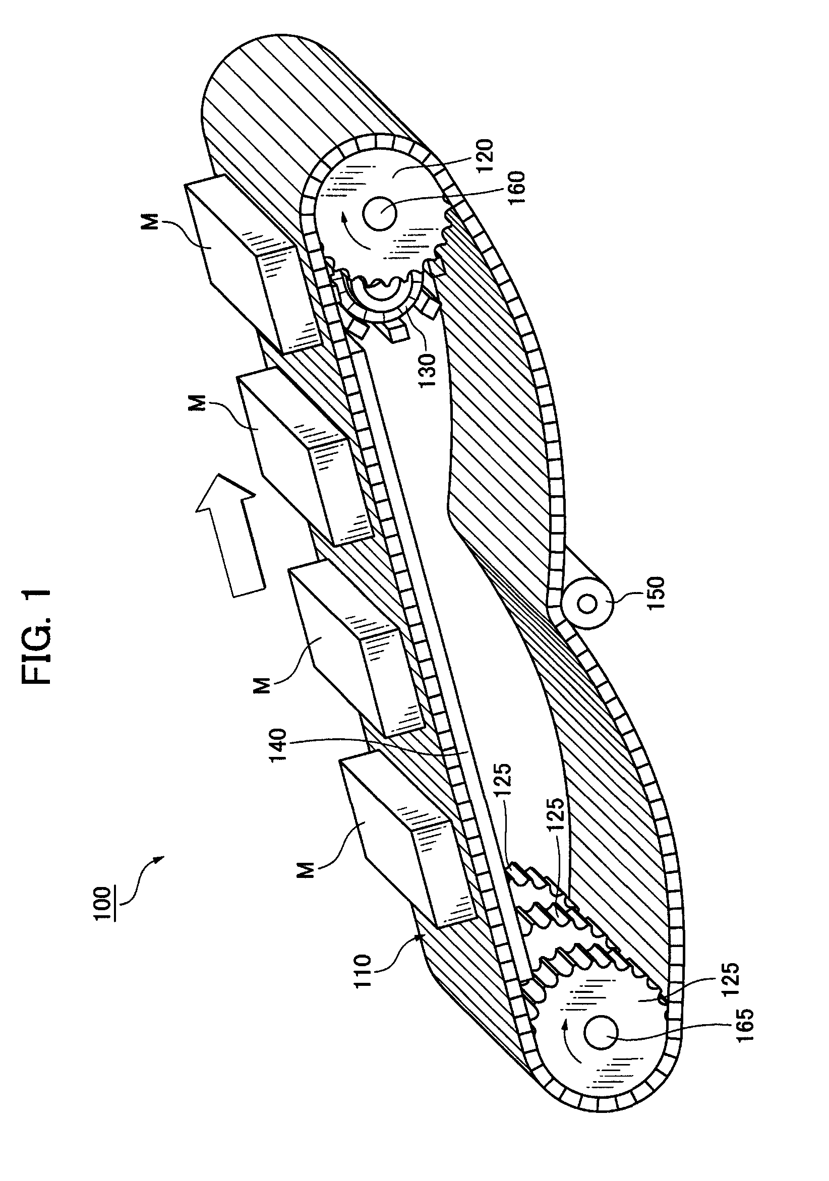
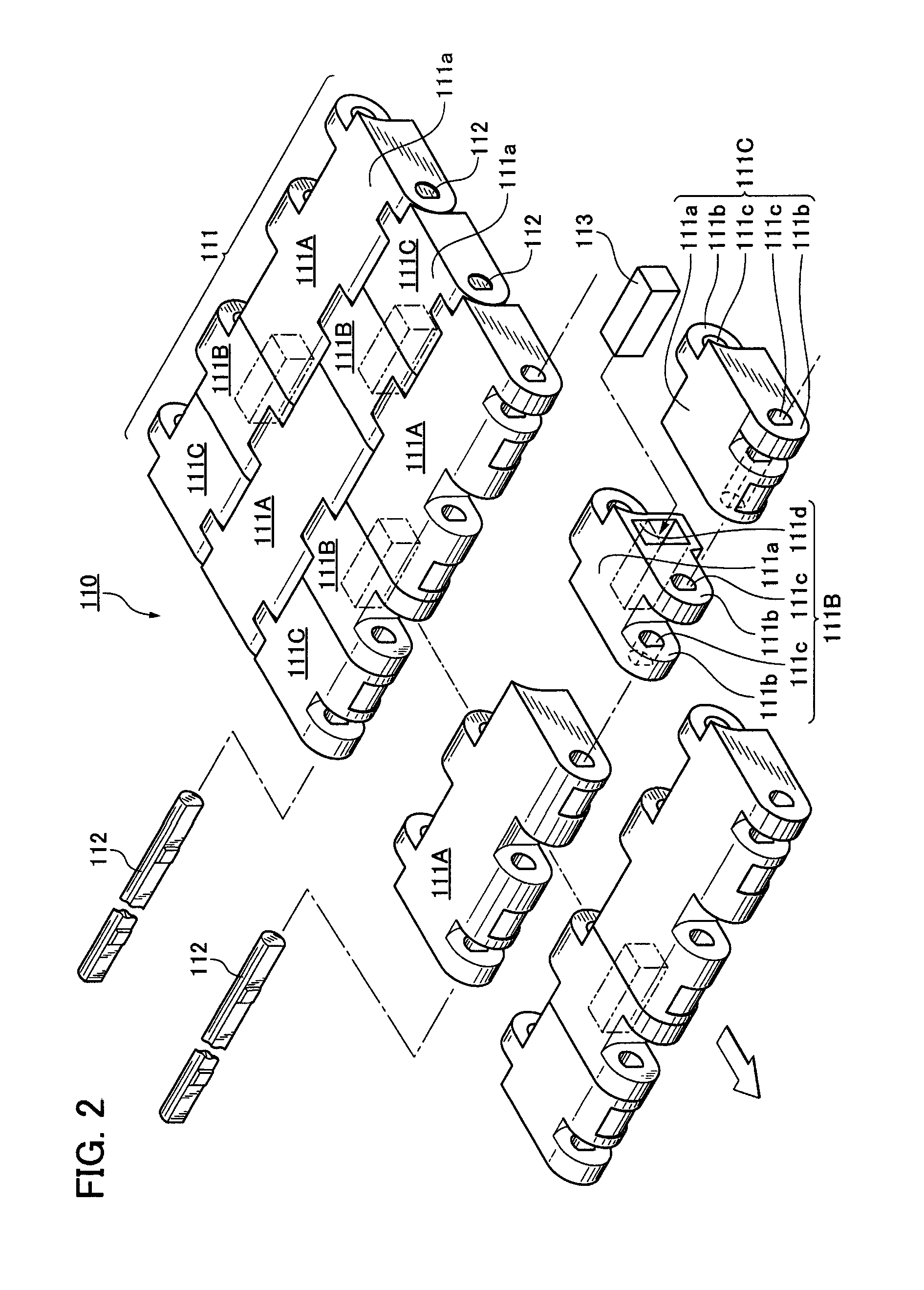
[0051]A first embodiment of a chain conveyor system of the invention will be explained with reference to FIGS. 1 through 6B. As shown in FIG. 1, the chain conveyor system 100 of the first embodiment of the invention comprises a conveyor chain 110 and sprockets 120 that engage with and turn the conveyor chain 110. The conveyor chain 110 comprises a large number of synthetic resin link modules 111 and link pins 112 for linking the link modules with each other in a chain longitudinal direction and conveys metallic magnetic articles M by attracting and retaining the articles on conveying surfaces 111a thereof by magnetism in a conveyor line inclined upward.

[0052]Thus, the chain conveyor system 100 conveys the metallic magnetic articles M by securely attracting and retaining the articles while avoiding damages and vibration noise otherwise generated by impacts between the articles M and the synthetic resin link modules 111 of the conveyor chain 110 that synergistically ...

second embodiment

[Second Embodiment]

[0075]Next, a second embodiment of a chain conveyor system of the invention will be explained with reference to FIGS. 7 and 8.

[0076]As compared to the chain conveyor system 100 of the first embodiment described above, the chain conveyor system of the second embodiment is different only in terms of the configuration of the article-separating auxiliary conveyor, and is not different basically in terms of the configuration of the other parts as shown in FIG. 7. Therefore, the same or corresponding parts of the second embodiment with those of the chain conveyor system 100 of the first embodiment will be denoted by reference numerals in 200 and a duplicate explanation thereof will be omitted here.

[0077]As shown in FIG. 7, article-separating auxiliary conveyor 230 of the chain conveyor system 200 of the present embodiment extends from the terminal discharge area to the preceding straight discharge area of the main conveyor chain 210. Two sets of the article-separating m...


PUM


Abstract

For a chain conveyor system having a main conveyor having links with an inclined or a slippery wet conveying run extending from a feed end to a discharge end capable of securely attracting and retaining metallic magnetic articles on the run by article-attracting magnet pieces in selected links for attracting and retaining the articles on the run. An auxiliary conveyor for enabling separation of the articles from the conveyor at the discharge end of the run by releasing attraction of the articles. The auxiliary conveyor has links which register with the main conveyor links at the discharge end of the main conveyor system. The registering links of the auxiliary conveyor have article-separating elements operable to reduce the magnetic force of the magnet pieces at the discharge end of the run to enable separation of the conveyed articles from the main conveyor.

Description

CROSS REFERENCE TO RELATED APPLICATIONS[0001]This application claims the foreign priority benefit under Title 35, United States Code, §119(a)-(d) of Japanese Patent Application No. 2011-126593, filed on Jun. 6, 2011 in the Japan Patent Office, the disclosure of which is herein incorporated by reference in its entirety.BACKGROUND OF THE INVENTION[0002]1. Field of the Invention[0003]The present invention relates to a chain conveyor system for loading and conveying articles to be conveyed (referred to simply as articles hereinafter) and more specifically to a chain conveyor system for conveying metallic magnetic articles by securely attracting and retaining the articles even on such a conveyor line inclined upward or downward or on a slippery wet conveyor line.[0004]2. Related Art[0005]Conventionally, there has been known a chain conveyor system for conveying magnetically attractive articles so as not fall by using a magnet-backed chain having a large number of attractive magnet units ...

Claims


Application Information

Patent Timeline
Patent Type & Authority Patents(United States)
IPC IPC(8): B65G23/18
CPCB65G23/18B65G15/58B65G17/46
Inventor OZAKI, HAJIME
Owner TSUBAKIMOTO CHAIN CO
Why Eureka
Try Eureka