Marine propulsion device

a propulsion device and marine technology, applied in the direction of gearing, vessel construction, hoisting equipment, etc., can solve the problems of reduced durability of the motive force transmission system during a normal motion, infiltration of water into the engine, and time lag, so as to prevent the relative rotation between the motive force transmission system and the housing section, prevent the occurrence and prevent the effect of the inversion phenomenon

Inactive Publication Date: 2013-11-28
YAMAHA MOTOR CO LTD
View PDF2 Cites 7 Cited by
  • Summary
  • Abstract
  • Description
  • Claims
  • Application Information

AI Technical Summary

Benefits of technology

[0012]In a marine propulsion device according to a preferred embodiment of the present invention, the clutch connects the motive force transmission system and the housing section during the reverse rotation of the motive force transmission system. As a result of this arrangement, the relative rotation between the motive force transmission system and the housing section is prevented. That is, occurrence of the inversion phenomenon is prevented. Furthermore, it is possible to swiftly and effectively prevent an occurrence of the inversion phenomenon since detection of the inversion phenomenon and control of the shift state are not necessary. In addition, the clutch opens the connection of the motive force transmission system and the housing section during normal rotation of the motive force transmission system. As a result of this arrangement, the clutch permits the relative rotation between the motive force transmission system and the housing section during normal rotation of the motive force transmission system. Accordingly, it is not necessary to segment the upstream portion and the downstream portion of the clutch. As a result, it is possible to maintain the durability of the motive force transmission system.

Problems solved by technology

As a result, there is a possibility that the durability of the motive force transmission system will be reduced during a normal motion since a portion that includes the one-way clutch is weak.
As a result, a time lag occurs until the motive force in the reverse direction is blocked, and there is a possibility that infiltration of water into the engine will occur during the time lag.

Method used


Image

  • Marine propulsion device
  • Marine propulsion device
  • Marine propulsion device

Examples


Embodiment Construction

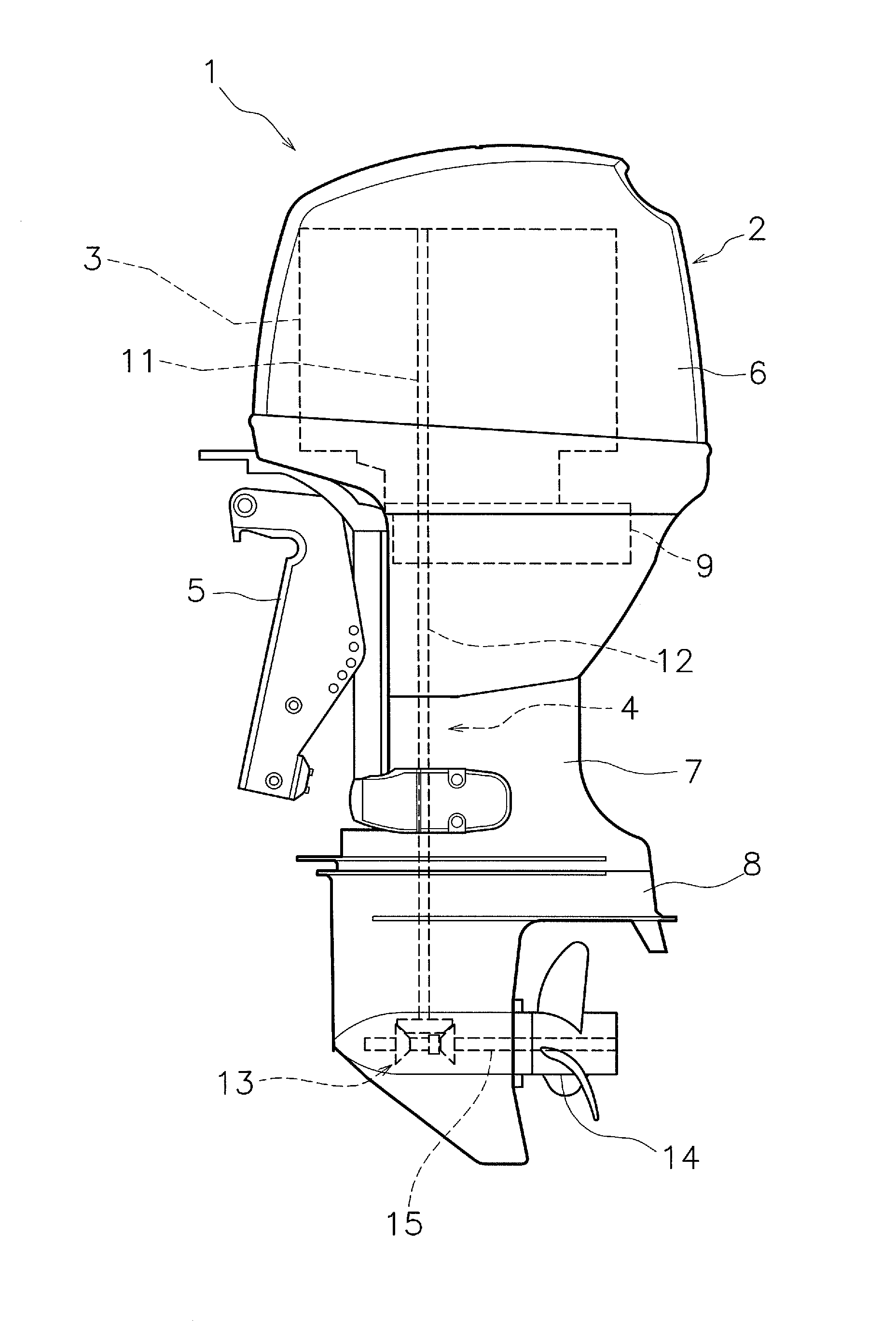
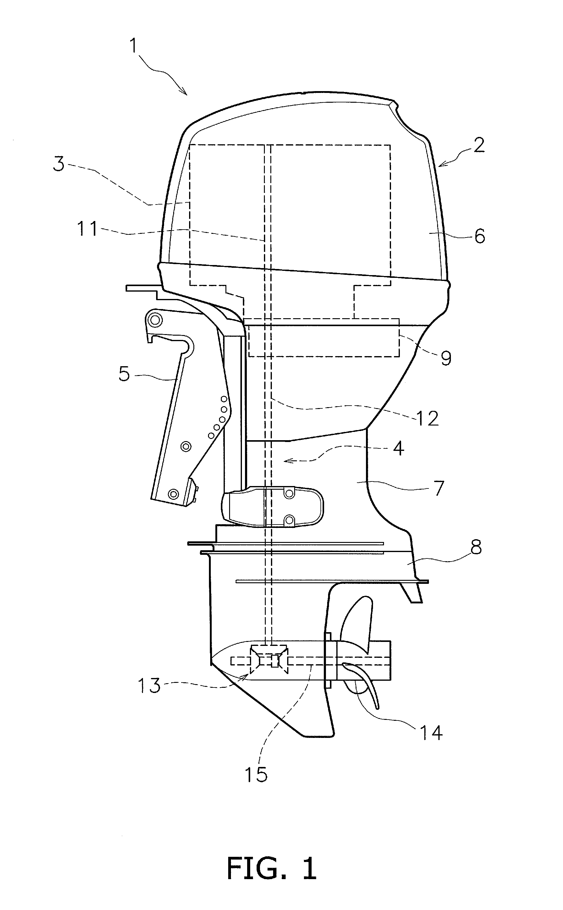
[0027]Below, a marine propulsion device according to a first preferred embodiment of the present invention will be described with reference to the drawings. FIG. 1 is a side view diagram illustrating a marine propulsion device 1 according to the first preferred embodiment of the present invention. The marine propulsion device 1 is preferably an outboard motor. The marine propulsion device 1 includes an engine cover 6, an upper casing 7, a lower casing 8, an engine 3, and a bracket 5. The engine cover 6 houses the engine 3. The upper casing 7 is disposed below the engine cover 6. The lower casing 8 is disposed below the upper casing 7. The marine propulsion device 1 is attached to a boat (not shown) via the bracket 5.

[0028]The engine 3 is disposed within the engine cover 6. The engine 3 is disposed on an exhaust guide 9. The exhaust guide 9 is disposed within the upper casing 7. For example, the engine 3 is a multicylinder engine, and includes a plurality of cylinders, a crank shaft ...


PUM


Abstract

A marine propulsion device includes a motive force transmission system, a propeller shaft, a housing section, and a clutch. The motive force transmission system includes a crank shaft and a drive shaft which transmits a motive force from the crank shaft. The propeller shaft transmits the motive force from the drive shaft. The housing section houses the motive force transmission system. The clutch is attached between the motive force transmission system and the housing section. The clutch permits relative rotation between the motive force transmission system and the housing section by opening a connection between the motive force transmission system and the housing section during normal rotation of the motive force transmission system. The clutch prevents relative rotation between the motive force transmission system and the housing section by connecting the motive force transmission system and the housing section during a reverse rotation of the motive force transmission system.

Description

BACKGROUND OF THE INVENTION[0001]1. Field of the Invention[0002]The present invention relates to a marine propulsion device.[0003]2. Description of the Related Art[0004]In an outboard motor, it is possible for a phenomenon to occur in which an engine is driven in a reverse direction (referred to below as an “inversion phenomenon”) by the propeller being rotated in a reverse orientation to a drive direction due to a torque applied by a water current. The cause for the occurrence of such an inversion phenomenon is described below. First, a boat operator sets a shift state to a neutral position in order to decelerate during forward progression. However, when a boat continues forward progression due to inertia, the propeller rotates normally due to water current hitting against the propeller. Next, the boat operator sets the shift state to a reverse position in order to further decelerate. At this time, if a rotation torque of the propeller due to the water current is larger than the en...

Claims


Application Information

Patent Timeline
Patent Type & Authority Applications(United States)
IPC IPC(8): B63H23/30
CPCB63H23/30B63H20/20Y10T74/19642Y10T74/19693
Inventor TANAKA, SEIICHIOGUMA, TAKAHIROOKABE, YOSHIHIKO
Owner YAMAHA MOTOR CO LTD
Why Eureka
Try Eureka