Method for Manufacturing a Reflector, Preferably for the Solar Energy Field

a technology of specular reflectors and manufacturing methods, applied in solar heat systems, solar-ray concentration, lighting and heating apparatus, etc., can solve the problems of small manufacturing tolerances of the support structure, non-negligible impact on the manufacturing cost, and the inability to hold the mirror

Active Publication Date: 2013-11-28
COMMISSARIAT A LENERGIE ATOMIQUE ET AUX ENERGIES ALTERNATIVES
View PDF1 Cites 18 Cited by
  • Summary
  • Abstract
  • Description
  • Claims
  • Application Information

AI Technical Summary

Benefits of technology

[0013]The solution according to the present invention enables very high manufacturing tolerances to be adopted for the support structure, without this being detrimental for the maintenance of the mirror's shape. Indeed, the metal links, whatever their shape, may be moved with high amplitudes during the adjustment step and / or after it, without this having any effect on the rigidity with which the mirror is held after the method is implemented. This therefore contrasts with the known solutions of the prior art, in which only blocks of adhesive are interposed between the mirror and the support structure.
[0035]This embodiment is particularly advantageous in that it enables the support structure to be reused easily when the mirror must be changed.

Problems solved by technology

Nevertheless, this requires very small manufacturing tolerances for the support structure, which has a non-negligible impact on the manufacturing cost.
However, the use of blocks of adhesive of substantial volume leads to problems in respect of the mirror's ability to be held on its structure, and is not therefore recommended.
In particular, in places where the adhesive is too bulky, its lack of rigidity may create a local deformation of the mirror, which is necessarily accompanied by a deterioration of the optical properties provided by it.
Finally, the heating required to soften the blocs of adhesive constitutes an additional constraint in the manufacturing method, in addition to which it is also likely to generate residual shape defects, due to shrinkages which may be seen during cooling.
In addition, the mirror may be disassembled only by reheating the deformed blocks of adhesive, which also increases the complexity of this disassembly operation.

Method used


Image

  • Method for Manufacturing a Reflector, Preferably for the Solar Energy Field
  • Method for Manufacturing a Reflector, Preferably for the Solar Energy Field
  • Method for Manufacturing a Reflector, Preferably for the Solar Energy Field

Examples


Embodiment Construction

[0010]The purpose of the invention is therefore to provide at least partially a solution to the disadvantages mentioned above, compared with the embodiments of the prior art.

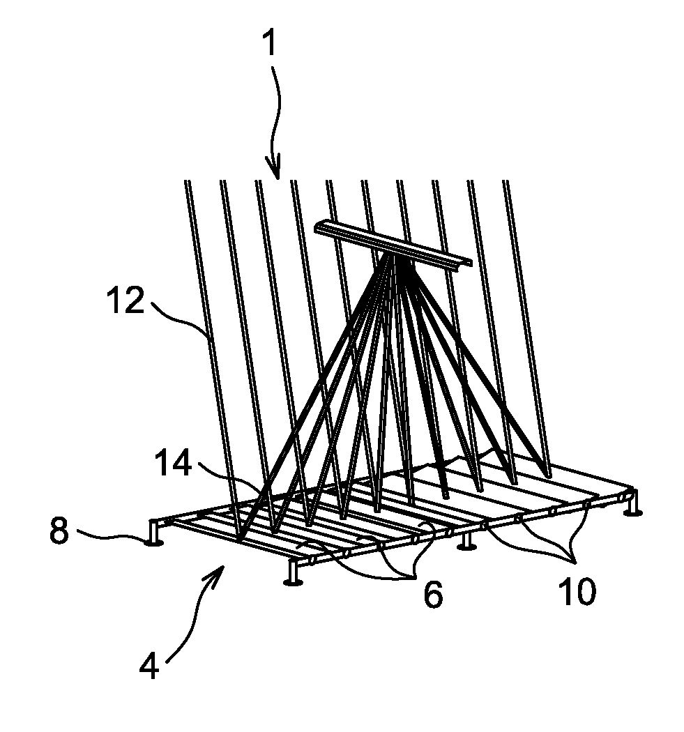
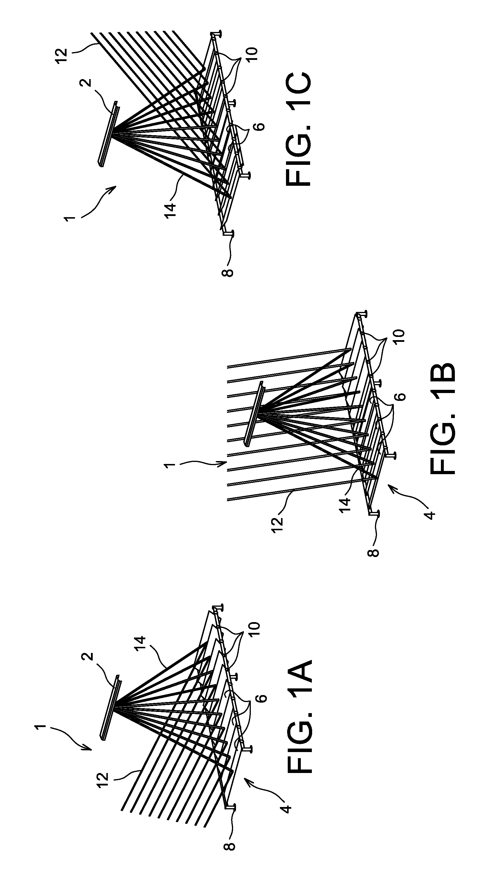
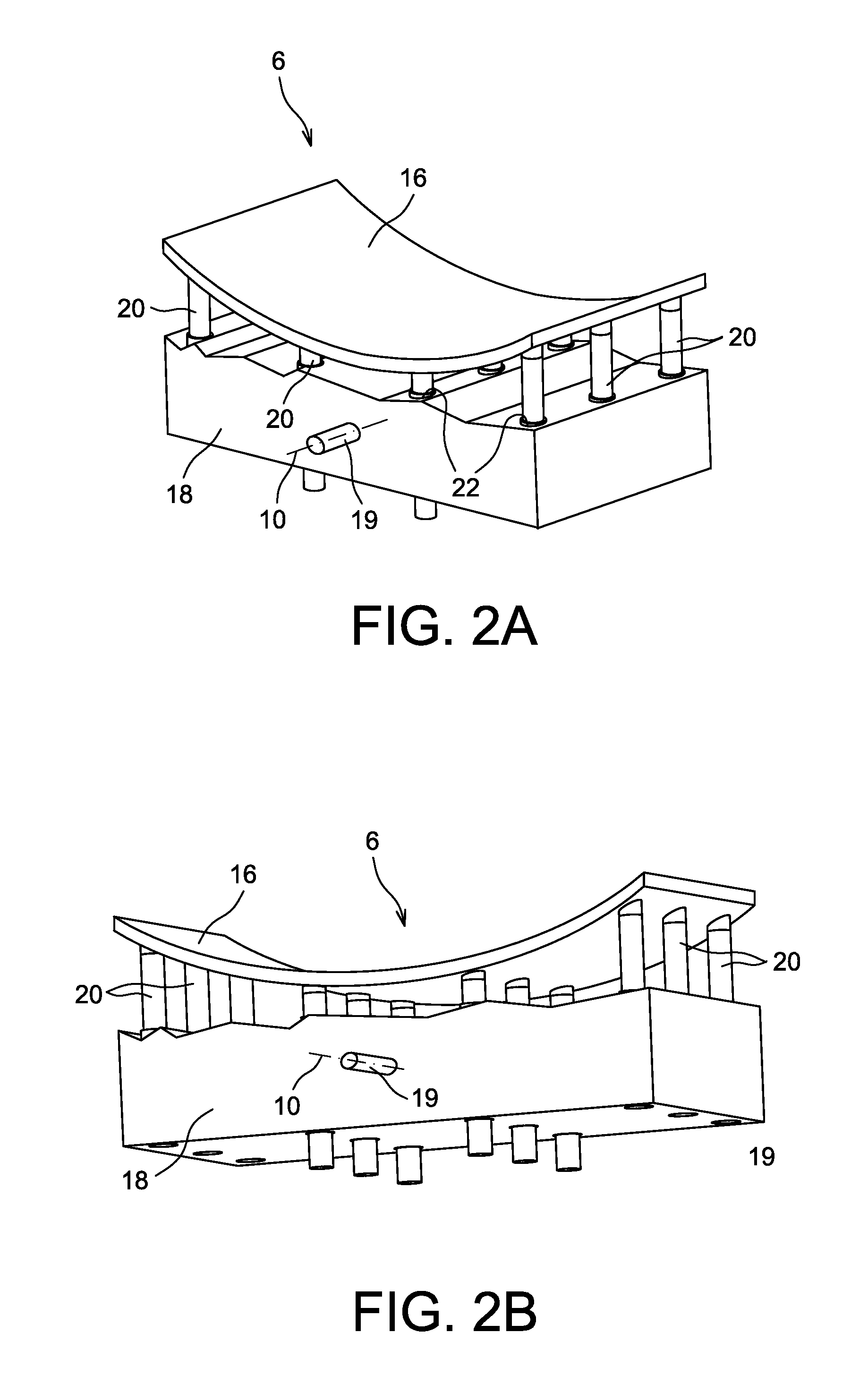
[0011]To accomplish this, a first object of the invention is a method of manufacturing a reflector including a mirror supported by a support structure, where the said method includes a method of positioning the mirror relative to the said support structure by relative movement of a mould supporting the mirror, relative to the said support structure.

[0012]According to the invention, the method also includes a step of adjustment of multiple links between the mirror and the support structure, in a position of secure attachment in which they are intended to be securely attached to the mirror and to the support structure, where this step of adjustment, accomplished during the said step of positioning of the mirror and / or after this step, leads to a movement of at least a proportion of, and preferably all, the links r...


PUM

PropertyMeasurementUnit
thickaaaaaaaaaa
thickaaaaaaaaaa
thickaaaaaaaaaa

Abstract

The invention relates to a method of manufacturing a reflector (6) including a mirror (16) supported by a support structure (18), where the said method includes a step of positioning the mirror relative to the said support structure by moving a mould (30) supporting the mirror relative to the said structure, According to the invention, the method also includes a step of adjustment of multiple links (20) between the mirror and the structure, implemented during the step of positioning of the mirror, and / or after this step, and causing at least a proportion of the links to be moved relative to the structure (18).

Description

TECHNICAL FIELD[0001]The present invention relates to the field of manufacture of specular reflectors to reflect and direct light.[0002]It relates in particular to the manufacturer of reflectors the mirror support structure of which is intended to be mobile, in order that it may direct the light received at different angles. Such reflectors, whether or not they have a mobile support structure, may be used to produce fields of reflectors, for example of the Fresnel type.[0003]The invention applies in particular to the field of solar energy, in particular for the production of systems including a solar collector, and also a field of reflectors concentrating solar radiation on to the collector.STATE OF THE PRIOR ART[0004]When manufacturing a reflector including a mirror supported by a support structure, a mould is habitually provided on which the mirror is temporarily assembled, where the mould gives this mirror its final shape. A step of positioning of the mirror relative to the rear ...

Claims


Application Information

Patent Timeline
Patent Type & Authority Applications(United States)
IPC IPC(8): G02B7/183G02B7/182F24S23/70
CPCG02B7/183G02B7/182F24S23/82F24S2023/872G02B27/62Y02E10/40Y10T29/49826
Inventor VIDAL, FREDERICCOUTURIER, RAPHAEL
Owner COMMISSARIAT A LENERGIE ATOMIQUE ET AUX ENERGIES ALTERNATIVES
Why Eureka
Try Eureka