
Connector

Active Publication Date: 2013-11-28
JAPAN AVIATION ELECTRONICS IND LTD
View PDF6 Cites 2 Cited by
  • Summary
  • Abstract
  • Description
  • Claims
  • Application Information

AI Technical Summary

Benefits of technology

The invention aims to solve problems of position offset and pitch narrowing of conductive portions in connectors. The invention introduces a connector that prevents position offset and achieves pitch narrowing of the conductive portions. By designing a beam with engaging portions that perpendicularly cross the connecting members, the connector is supported at a portion inside the connecting members, reducing unwanted deformation and offset in position of the conductive portions. Additionally, the invention keeps constant the distance between the conductive portions of the connecting members without providing an inter-pitch portion, resulting in pitch narrowing of the conductive portions in the third direction.

Problems solved by technology

However, this causes a problem that pitch narrowing of the conductors 124 in the third direction Z is hindered.

Method used


Image

  • Connector
  • Connector
  • Connector

Examples


embodiments

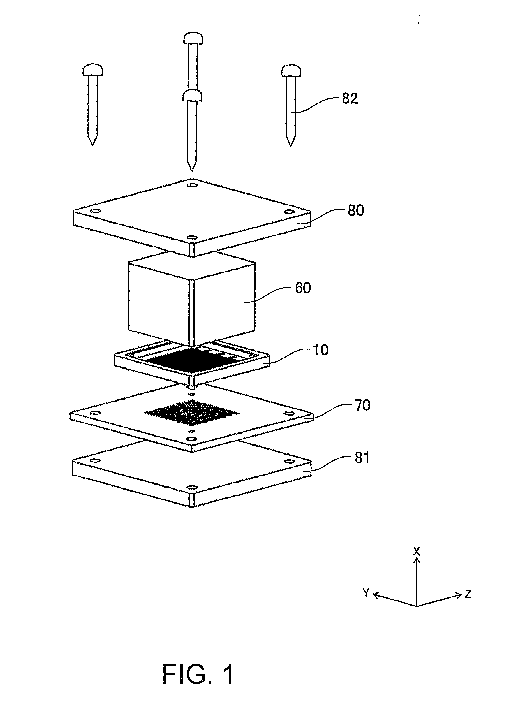
[0039]As shown in FIG. 1, a connector 10 according to a first embodiment of this invention is adapted to be interposed between a first connection object 60 formed as an IC package and a second connection object 70 formed as a lower board, thereby establishing electrical connection between the first and second connection objects 60 and 70. In FIG. 1, numeral 80 denotes an upper stiffener, numeral 81 denotes a lower stiffener, and numeral 82 denotes screws for fixing the upper and lower stiffeners 80 and 81 together. While the connector 10 is described as an actual mounting connector in this embodiment, it may alternatively be used as an inspection connector.

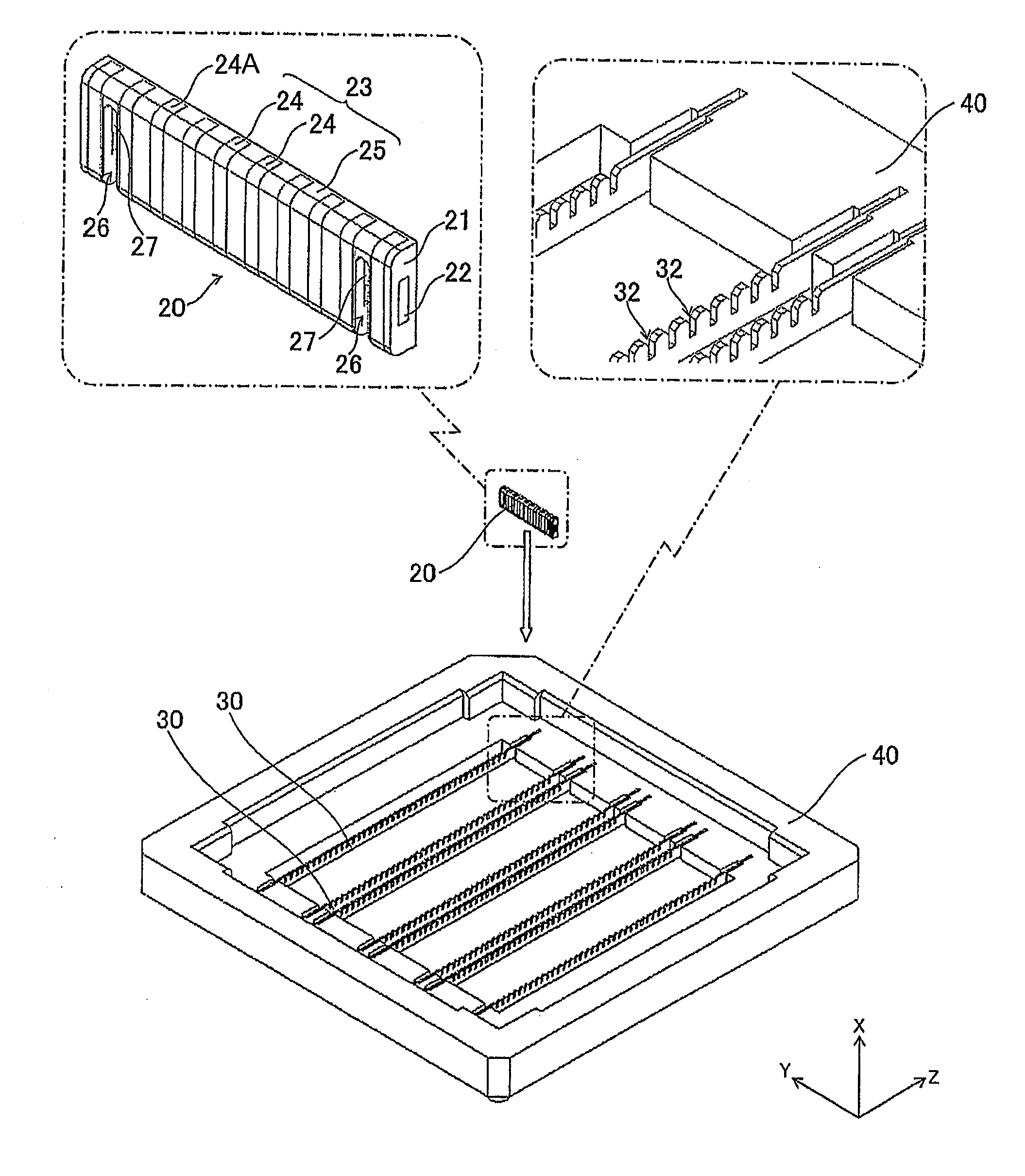
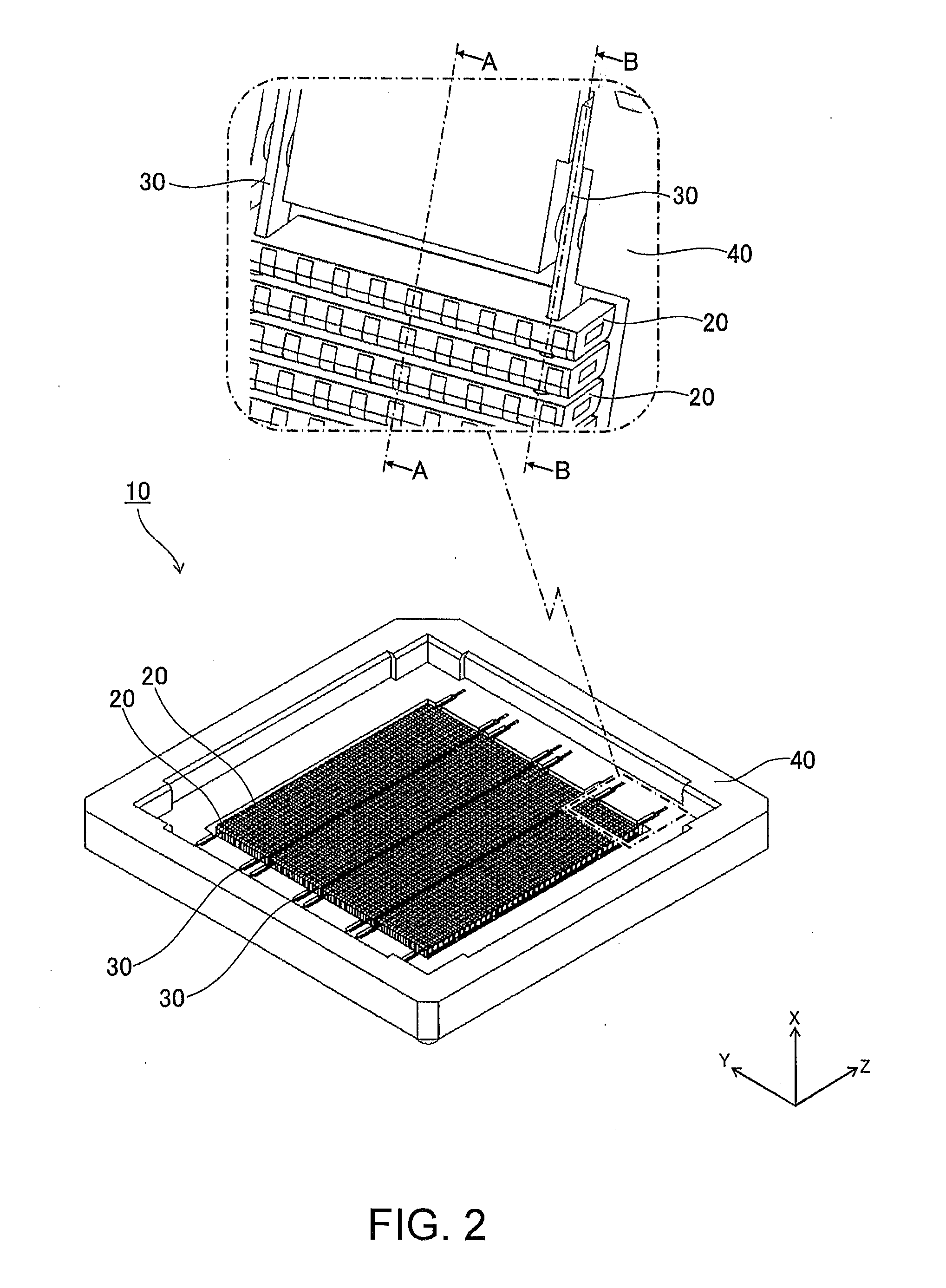
[0040]As shown in FIGS. 2 to 4, the connector 10 comprises a plurality of connecting members 20, a plurality of beams 30 holding the connecting members 20, and a frame 40 supporting the beams 30.

[0041]As shown in FIG. 2, the connecting members 20, each having a longitudinal direction extending in the second direction Y, are arrang...


PUM


Abstract

A connector is adapted to be interposed between a first connection object and a second connection object for establishing electrical connection therebetween. The connector comprises a plurality of connecting members each having a plurality of elastically deformable conductive portions formed at a predetermined interval along a longitudinal direction thereof, a beam holding the connecting members, and a support portion supporting the beam. The connecting members, each having its longitudinal direction extending in a second direction perpendicular to a first direction in which the first and second connection objects and are caused to approach each other, are arranged in a third direction perpendicular to the first and second directions. The beam is disposed with its longitudinal direction extending in the third direction so as to perpendicularly cross the connecting members. The beam has engaging portions, engaging with the connecting members, at positions where the beam crosses the connecting members.

Description

[0001]This application is based upon and claims the benefit of priority from Japanese patent application No. 2012-119166, filed on May 25, 2012, the disclosure of which is incorporated herein in its entirety by reference.TECHNICAL FIELD[0002]This invention relates to a connector which is interposed between connection objects for establishing electrical connection therebetween.BACKGROUND ART[0003]As shown in FIGS. 15 and 16, there has conventionally been known a connecting device 110 which is interposed between a pair of connection objects 160 and 170 for establishing electrical connection therebetween (see, e.g. JP-A-2007-95632 (Patent Document 1)). The connecting device 110 comprises a plurality of connecting members 120 each having a longitudinal direction extending in a second direction Y perpendicular to a first direction X in which the connection objects 160 and 170 are caused to approach each other. The connecting members 120 are arranged in a third direction Z perpendicular t...

Claims


Application Information

Patent Timeline
IPC IPC(8): H01R13/40
CPCH01R13/40H01R12/7076H01R13/2414H01R12/71H01R13/24H01R33/76
Inventor KOJIMA, TAKERUTAKAHASHI, TAKESHI
Owner JAPAN AVIATION ELECTRONICS IND LTD
Learn More