
Monte Carlo and Iterative Methods for Determination of Tissue Oxygen Saturation

a tissue oxygen saturation and iterative method technology, applied in the field of optical systems, can solve problems such as unstable tissue oxygenation state of patients, and achieve the effect of quick determination of optical properties of tissue under investigation

Active Publication Date: 2013-11-28
VIOPTIX
View PDF2 Cites 36 Cited by
  • Summary
  • Abstract
  • Description
  • Claims
  • Application Information

AI Technical Summary

Benefits of technology

The patent describes a device that uses simulated reflectance curves to quickly determine the optical properties of tissue. This allows for the further determination of the oxygenated and deoxygenated hemoglobin concentrations, as well as the oxygen saturation of the tissue. The device uses a scattering coefficient and absorption coefficients for the tissue to determine the oxygen saturation value. This is done by creating a look-up table of oxygen saturation values based on the absorption coefficients and a range of probable total hemoglobin, melanin, and oxygen saturation values. The device then converts the absorption coefficients to a unit vector and compares it to the look-up table to find the best fit for the oxygen saturation of the tissue.

Problems solved by technology

Thus, oximeters are often used in clinical settings, such as during surgery and recovery, where it may be suspected that the patient's tissue oxygenation state is unstable.
While existing oximeters have been sufficient for post-operative tissue monitoring where absolute accuracy is not critical and trending data alone is sufficient, accuracy is, however, required during surgery in which spot-checking can be used to determine whether tissue might remain viable or needs to be removed.

Method used


Image

  • Monte Carlo and Iterative Methods for Determination of Tissue Oxygen Saturation
  • Monte Carlo and Iterative Methods for Determination of Tissue Oxygen Saturation
  • Monte Carlo and Iterative Methods for Determination of Tissue Oxygen Saturation

Examples


Embodiment Construction

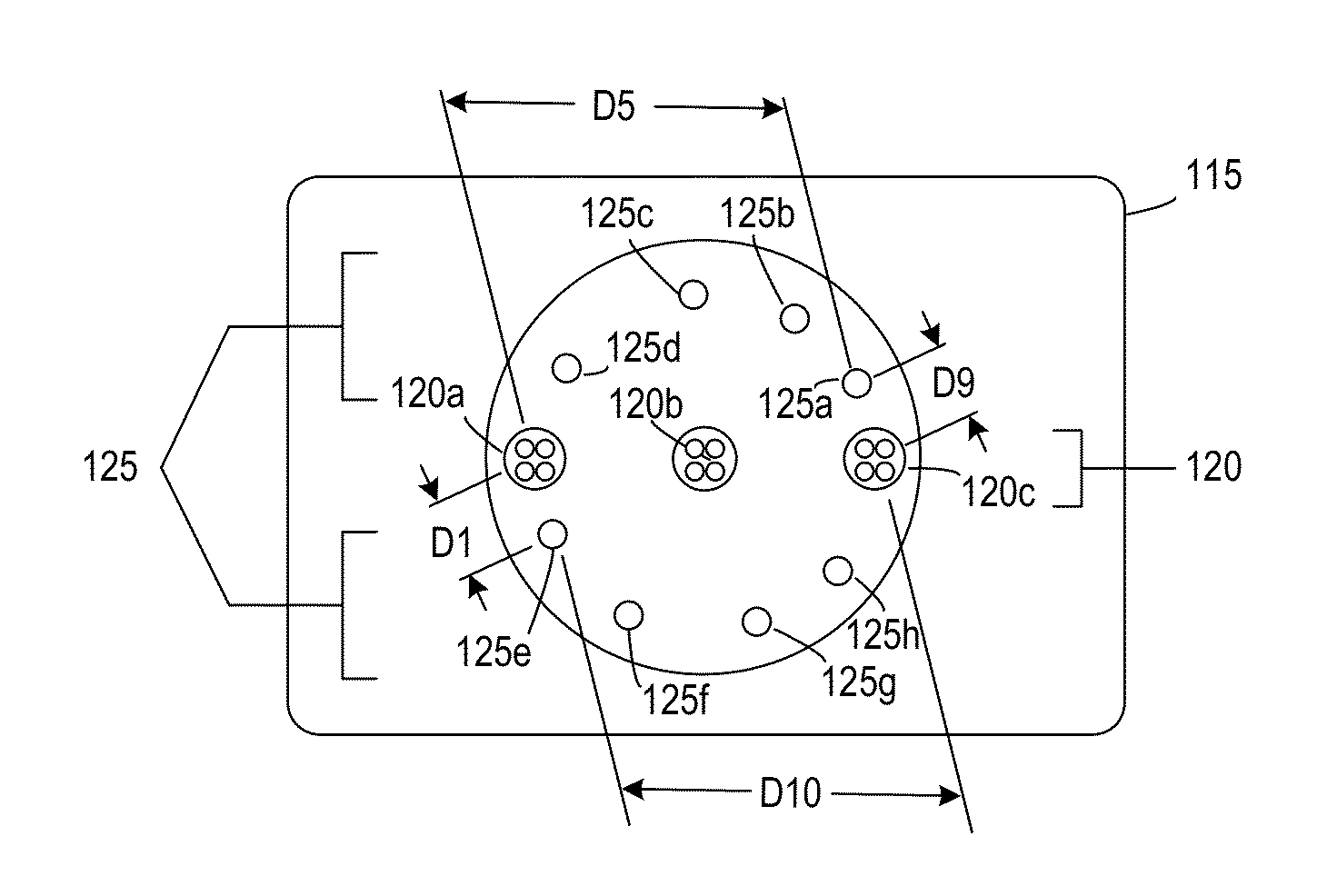
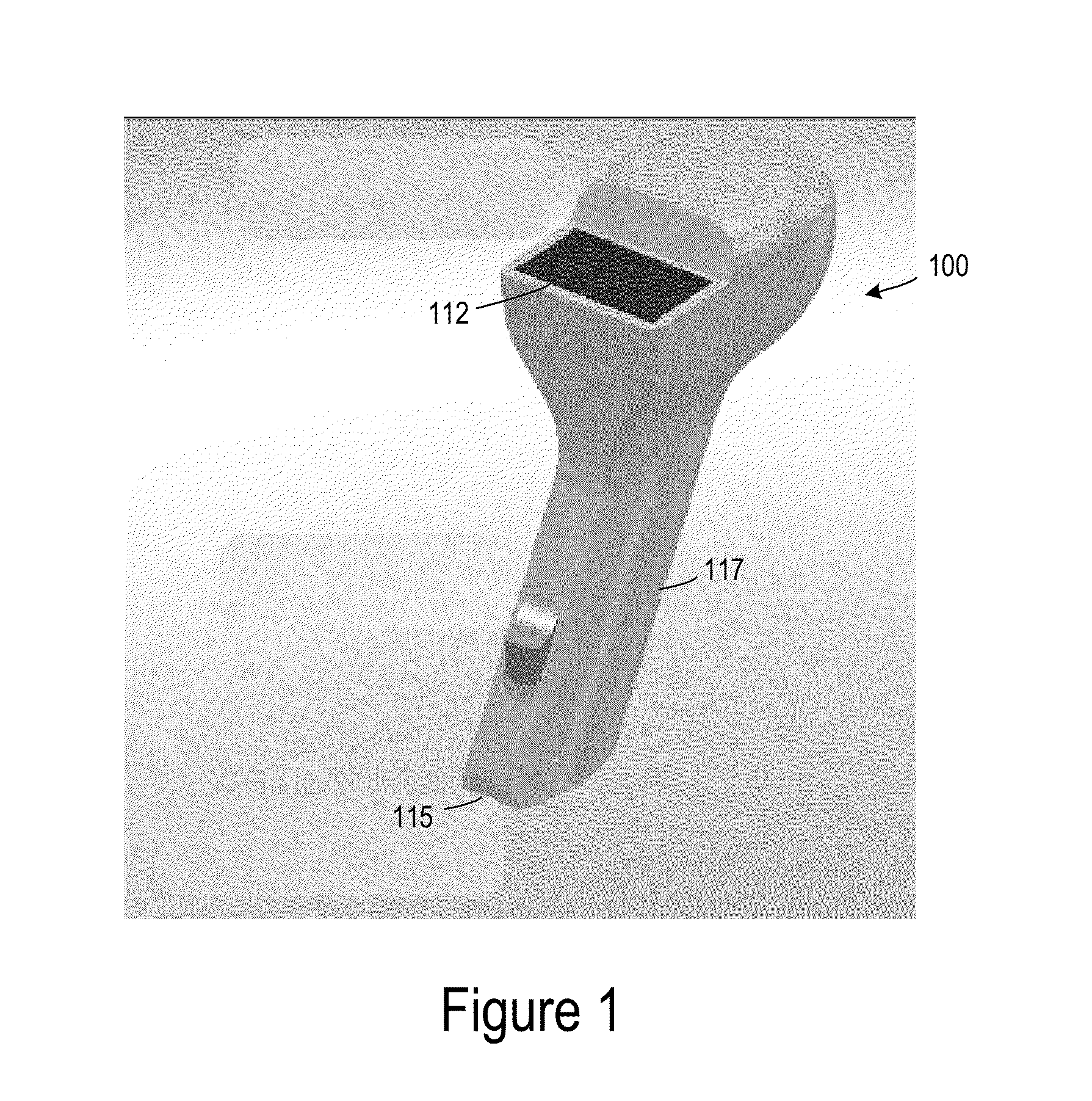
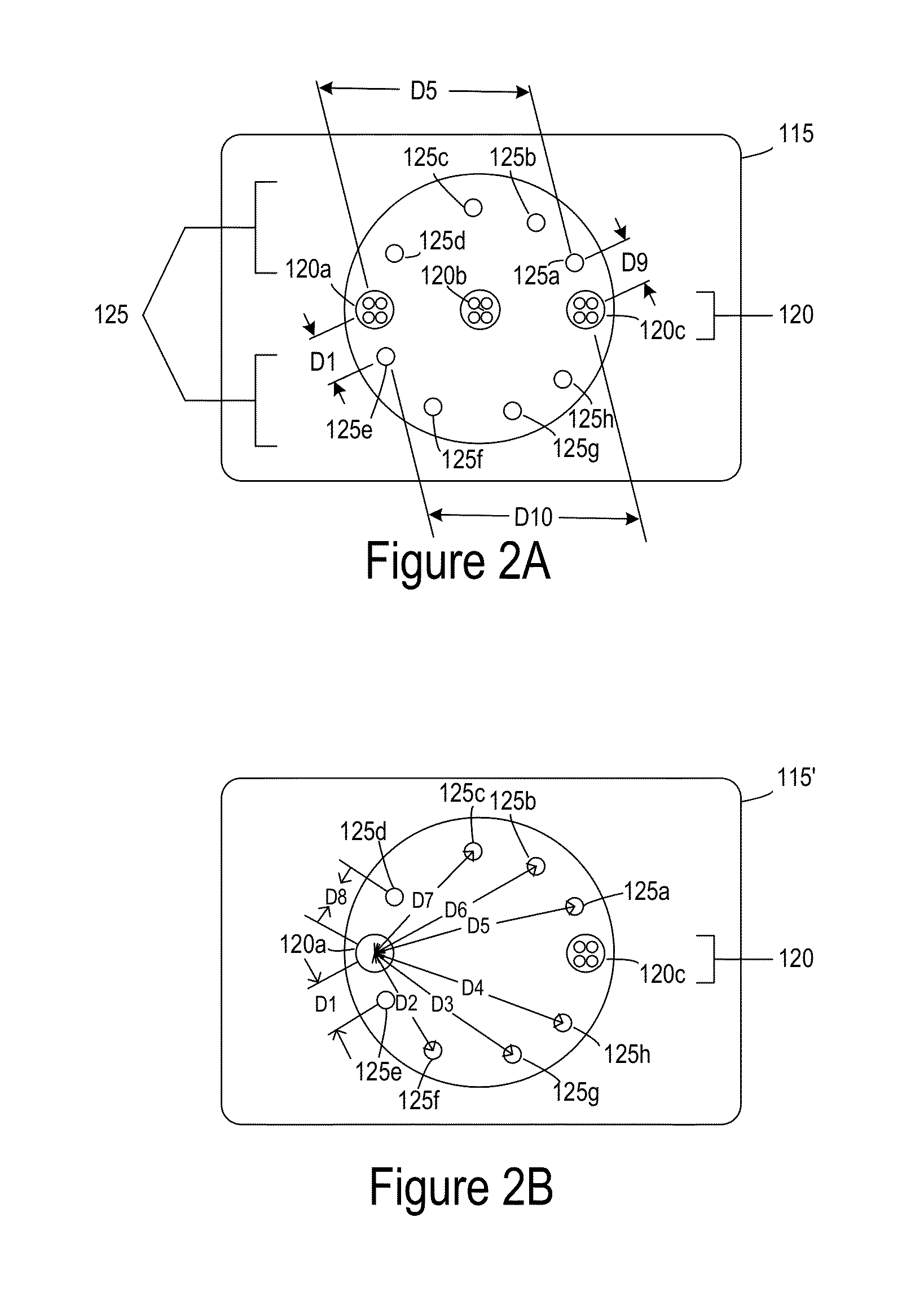
[0024]FIG. 1 is a simplified image of a tissue oximetry device 100 according to one embodiment. Tissue oximetry device 100 is configured to make tissue oximetry measurements, such as intraoperatively and postoperatively. Tissue oximetry device 100 may be a handheld device that includes a tissue oximetry probe 115 (also referred to as a sensor head), which may be positioned at an end of a sensing arm 117. Tissue oximetry device 100 is configured to measure the oxygen saturation of tissue by emitting light, such as near-infrared light, from tissue oximetry probe 115 into tissue, and collecting light reflected from the tissue at the tissue oximetry probe.

[0025]Tissue oximetry device 100 may include a display 112 or other notification device that notifies a user of oxygen saturation measurements made by the tissue oximetry device. While tissue oximetry probe 115 is described as being configured for use with tissue oximetry device 100, which is a handheld device, tissue oximetry probe 11...


PUM


Abstract

A method for determining oxygen saturation includes emitting light from sources into tissue; detecting the light by detectors subsequent to reflection; and generating reflectance data based on detecting the light. The method includes determining a first subset of simulated reflectance curves from a set of simulated reflectance curves stored in a tissue oximetry device for a coarse grid; and fitting the reflectance data points to the first subset of simulated reflectance curves to determine a closest fitting one of the simulated reflectance curves. The method includes determining a second subset of simulated reflectance curves for a fine grid based on the closest fitting one of the simulated reflectance curves; determining a peak of absorption and reflection coefficients from the fine grid; and determining an absorption and a reflectance coefficient for the reflectance data points by performing a weighted average of the absorption coefficients and reflection coefficients from the peak.

Description

CROSS-REFERENCE TO RELATED APPLICATIONS[0001]This patent application claims the benefit of U.S. provisional patent applications 61 / 642,389, 61 / 642,393, 61 / 642,395, and 61 / 642,399, filed May 3, 2012, and 61 / 682,146, filed Aug. 10, 2012, which are incorporated by reference along with all other references cited in this application.BACKGROUND OF THE INVENTION[0002]The present invention relates generally to optical systems that monitor oxygen levels in tissue. More specifically, the present invention relates to optical probes, such as oximeters, that include sources and detectors on sensor heads of the optical probes and that use locally stored simulated reflectance curves for determining oxygen saturation of tissue.[0003]Oximeters are medical devices used to measure oxygen saturation of tissue in humans and living things for various purposes. For example, oximeters are used for medical and diagnostic purposes in hospitals and other medical facilities (e.g., surgery, patient monitoring, ...

Claims


Application Information

Patent Timeline
Patent Type & Authority Applications(United States)
IPC IPC(8): A61B5/1455
CPCA61B5/1455A61B5/0075A61B5/14552A61B5/1495A61B2560/0431A61B5/74A61B90/39A61B5/14551A61B5/7405A61B5/742A61B5/7475A61B5/7282A61M35/003A61B5/72A61B5/14546A61B90/11A61B5/0059A61B5/7246A61B2090/395A61B2090/065A61B2090/306A61B5/1459A61B2560/0475A61B2562/0271A61B2562/166
Inventor BECHTEL, KATE LEEANNNISHIHARA, H. KEITH
Owner VIOPTIX
Learn More