
Femoral neck fracture implant

a technology of femoral neck and implant, which is applied in the field of fasteners and fastener assemblies, can solve the problems of damage to the hip joint, the perforation of the fastener, and the perforation of the femoral head of the fastener

Active Publication Date: 2013-11-28
DEPUY SYNTHES PROD INC
View PDF9 Cites 25 Cited by
  • Summary
  • Abstract
  • Description
  • Claims
  • Application Information

AI Technical Summary

Benefits of technology

The present invention is a bone fixation element that is used to support the healing of femoral neck fractures. It has a unique design that includes two channels: a central longitudinal channel and a side wall channel. The central channel is designed to receive a guide wire, while the side wall channel is designed to receive an anti-rotation member, such as a bone screw. The second channel prevents the femoral head from rotating relative to the implant shaft. The invention also includes a method of implanting the bone fixation assembly into a bone by inserting the implant shaft and then inserting the anti-rotation member through the side wall channel. The technical effects of this invention are improved stability and reduced risk of complications.

Problems solved by technology

After the fastener is fixed, medial migration of the femoral head relative to the neck fracture may cause an end of the rod-like fastener to perforate the femoral head and damage the hip-joint.

Method used


Image

  • Femoral neck fracture implant
  • Femoral neck fracture implant
  • Femoral neck fracture implant

Examples


Embodiment Construction

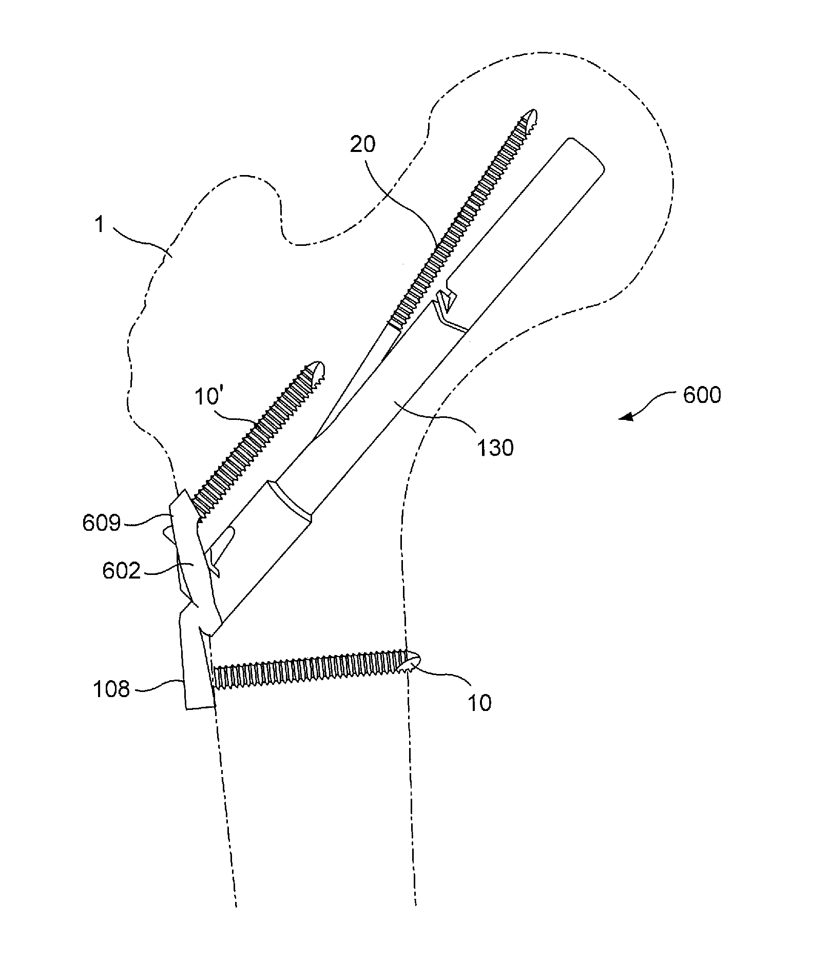
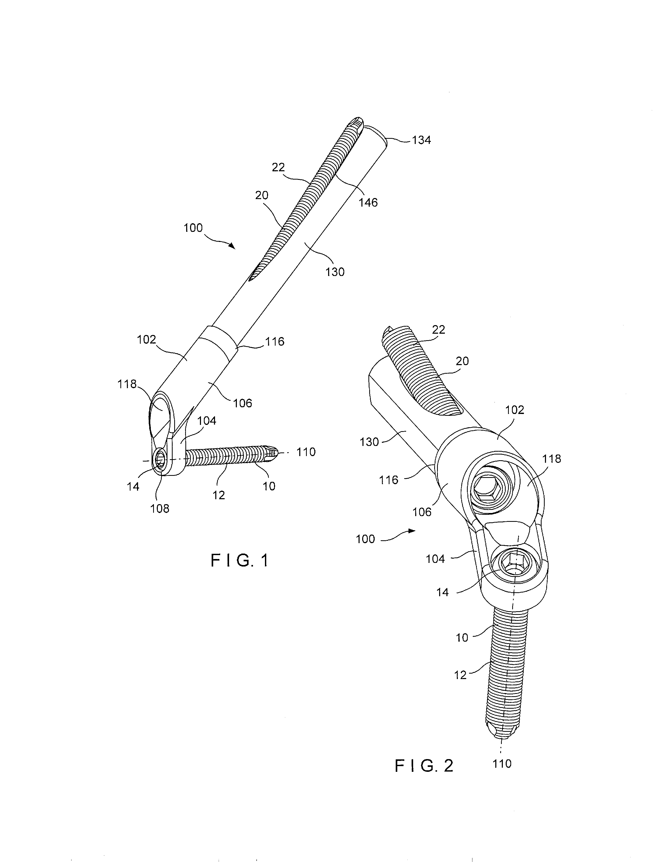
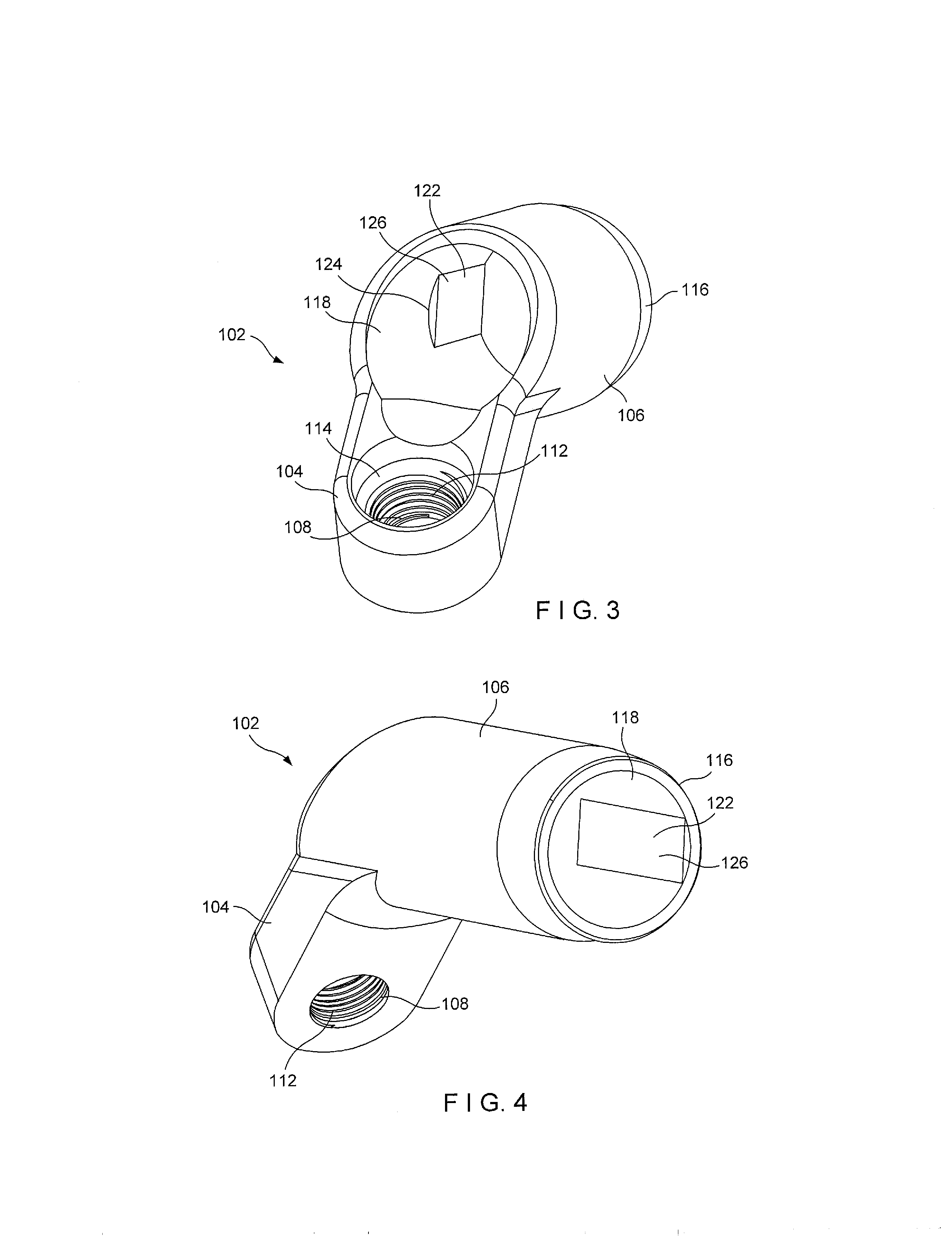
[0079]The present invention may be further understood with reference to the following description and the appended drawings, wherein like elements are referred to with the same reference numerals. The present invention relates to the treatment of fractures and, in particular, to devices for fixing femoral neck fractures. Exemplary embodiments of the present invention describe a bone plate having first portion positionable against an outer surface of a fractured or otherwise damaged bone and a second portion partially inserted into the bone. A first bone screw hole extends through the first portion and a second bone screw hole extends through the second portion. The second portion further receives a bone fixation shaft sized and dimensioned to extend across a fractured portion of the femoral neck into the femoral head. The bone fixation shaft includes a transverse opening extending through a side wall thereof along a transverse opening axis angled with respect to a bone fixation shaf...


PUM


Abstract

A bone fixation system comprises an elongated implant shaft extending from a proximal end to a distal end along a central longitudinal axis and including a first channel extending from the proximal end to a side opening formed in a side wall of the implant shaft along a first channel axis. The bone fixation system further comprises a bone plate having a first plate portion and a second plate portion, the first plate portion having a first opening extending therethrough along a first opening axis and the second plate portion having a second opening extending therethrough along a second opening axis, the second opening being configured to receive the implant shaft therethrough to permit insertion thereof into a head of a bone.

Description

PRIORITY CLAIM[0001]This application claims priority to U.S. Provisional Application Ser. No. 61 / 561,439 filed on Nov. 18, 2011 and entitled “Fastener” and U.S. Provisional Application Ser. No. 61 / 692,053 filed on Aug. 22, 2012 and entitled “Femoral Neck Fracture Implant,” the entire disclosures of which are incorporated herein by reference.FIELD OF THE INVENTION[0002]The present invention generally relates to fasteners, fastener assemblies, kits for fastener assemblies, methods of assembling fastener assemblies, and methods of implanting fastener assemblies in a bone.BACKGROUND[0003]Femoral neck fractures are often treated with a pin or other implant inserted into the femoral head along an axis of the femoral neck. One such product is the Stryker® Hansson® Pin System, which is a rod first and second ends separated from one another by a side wall with no threading on its outer surface. The Hansson® Pin has a hook deployable from a first end region for fixing the Hansson® Pin in the ...

Claims


Application Information

Patent Timeline
IPC IPC(8): A61B17/74
CPCA61B17/746A61B17/74A61B17/8605A61B17/8685A61B17/90A61B17/864A61B17/863A61B17/1721A61B17/8057
Inventor OVERES, TOM
Owner DEPUY SYNTHES PROD INC
Learn More